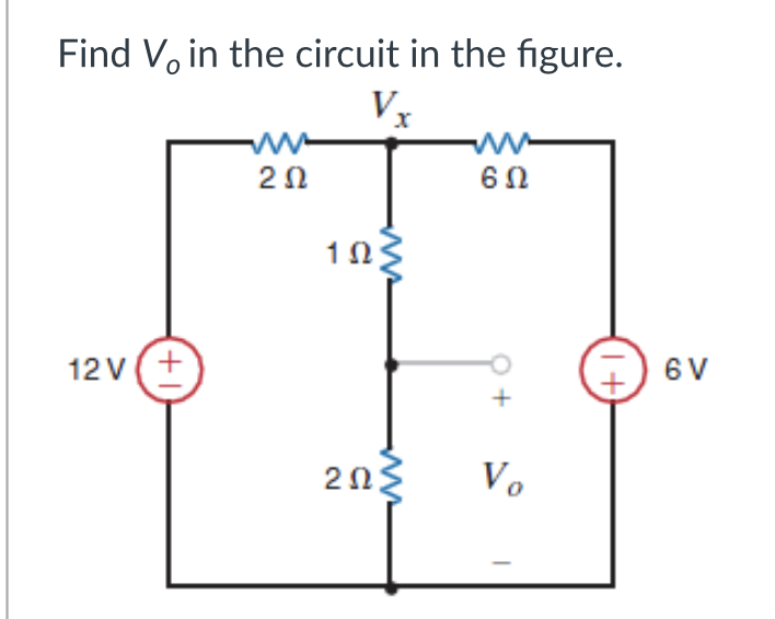
nd V, in the circuit in the figure. Vx ww 60 20 103 2v(+ 6 V Vo


Q: Ex. 804. A PD controller has a derivative gain of 38. What is the proportional gain if the zero is p...
A: The solution is given below
Q: J. q. Determine vo for (+) and G) cy de . Si (ov 1 h. Draw Vo. E IKI V. - lo V
A:
Q: Given the potential V = 10 sin 0 cos , (a) Find the electric flux density D at (2, 7/2, 0). (b) Calc...
A: We need to find out flux density and work done .
Q: ²+19s+59 ROC: –7< o< -2 (s+2)(s+7)' can be expressed in the form ¤(t) = A8(t) + BED«(t) + CeEu(-t). ...
A:
Q: 9. Determine Vo por (+) and (-) ayde. 1-skr 3. diodes D2 loksn 2 Vo b. Draw Vo. 2.5v - nov
A: “Since you have asked multiple question, we will solve the first question for you. If you want any s...
Q: 01 kn vit o Vo い a) Dekrmin Vo for Ct) () uele of vi b) Oraw V,
A: In this question, Input voltage waveform is given. Draw the output voltage waveform and output vol...
Q: An industrial plant consisting primarily of induction me 0.85 power factor lagging. Compute the requ...
A: Given Power S = 1200 KVA at 0.85 pf Ti determine the shunt capacitor required to improve power facto...
Q: Q, Solve te differehtial equntion by Laplace trems form. ý-y = t, y) = 1, ý(0) = 1
A: Since you have asked multiple questions in a single request, we will be answering only the 1st quest...
Q: A 2.5Ω and 2.8Ω resistors, connected in parallel, are in parallel with the series 3.2Ω and 2.2Ω load...
A:
Q: Solve for VcB 10 uF B = 60 10 uF Vo 1.2 ko 2.4 kQ ww ww
A:
Q: Find the Curent i4) for figures all initial Codition ore Zero below, absume 9)
A: Since you have asked multiple questions in a single request, we will be answering only the 1st quest...
Q: Find the Current i4) for figures below, assume all initial Condition ore Zero R. 10n vit) = ty 2
A: As per our guidelines we are supposed to be answer the first question only. Kindly repost the other ...
Q: / Point charges of 50NC, each are locateu at A(1, 0, 0), B(-1, 0, 0), C(O, 1, 0), and in free space....
A:
Q: 1. a) Use the mesh-current method to write a complete set of independent equations that could be use...
A: Given the circuit, as shown below: a) We need to use the mesh current method to write a complete se...
Q: 2. For the network shown in the figure and the applied source: liz lic IR R 3 kN X1 4 kN Xc 2 kN i; ...
A:
Q: 6. a) Use the mesh-current method to write a complete set of equations that could be used to solve t...
A: Mesh Analysis: Mesh analysis is also known as the mesh current method. It is a method for solving pl...
Q: ple Problems wo resistors vhen connected in series has a total resistance of 24
A:
Q: 4. Given: Rs 2202 Determine the range of Vi to maintain the Zener diodes in the "ON" state Vz R5 120...
A:
Q: Tdeal diodes Dz 1-5kr 3. 9. Determine Vo (-) ayde. For (+) and Vi Vo b. Draw Vo. 2.sv+ + 1av
A: This question is belong to clippers and clamper diode circuits. Analysis is to be done with differen...
Q: The unit of magnetic flux density B is; A a) Tesla per sq. m. (в) ь) Тesla C c) Weber d) Weber per s...
A: Magnetic flux is defined as a measure of the strength of a magnetic field over a given area. The uni...
Q: Find the transfer function, Vo(s) / Viſs) of the circuit. Given ALL R=1, ALL C=2 F R2 Fill in the bl...
A: We need to find out transfer function for given circuit
Q: DE MOIVRE'S THEOREM Copy the problems and show your full solutions on your answer sheet. Evaluate th...
A:
Q: 01 km 2) vit lov t. 古ら a) Dekrmin Ve for C+) ( yele f vi b) Oraw V
A:
Q: Directional Overcurrent Relay & Non-Directional Overcurrent Relay
A: When the current flowing through the device is more than the pickup current set for the device then,...
Q: From the circuit in Fig. 2.83, find I, the power dis- sipated by the resistor, and the power supplie...
A:
Q: Consider N masses connected by springs to each other and the walls on both sides. For simplicity, ch...
A: Coupled Oscillations: We have to start coupling oscillators together to get to waves. In the case of...
Q: TRUE OR FALSE: More than one output of a BCD-to-7 segment decoder/driver can be active at one time.
A: This BCD to seven segment decoder has four input lines (A, B, C, and D) and seven output lines (a, b...
Q: You have come across different characteristics and applications of antenna. With the knowledge, have...
A:
Q: A singe tore is wed to modulate FM transmiten. The tafal power is 450 watt into los2 sichia load. De...
A: We are authorized to answer three subparts at a time, since you have not mentioned which part you ar...
Q: Explain the operation of three phase induction machine. (Not too long). Define slip.
A: A three phase induction motor has a stator and a rotor. The stator carries a 3-phase winding called ...
Q: Determine Ibo, VGsa, and V Ds for the network of Fig. F. 40 V 3 kQ 22 M2 DO 2N4351 Vas m = 5 V (T) G...
A: Brief description: Field effect transistors are known high input impedance devices. Because of prese...
Q: Mention the characteristics of instrumentation amplifier using opamp What are the applications of th...
A: Instrumentation amplifier contain three op-amp. Out of 3, two will be inverting amplifier and third ...
Q: can you use an npn in a circuit and make it act as a pnp?
A: NPN circuit has p-type S.C. and is being sandwiched by two n-type S.C. in which holes are in minorit...
Q: Tdeal diodes D2 1-5kr 3. 9. Determine Vo For (H) and (-) ayde. Vi Vo b. Draw Vo. 2.sv - nov
A: This problem is belong to clippers and clamper
Q: Give reason why dc motor requires starter.
A: When a DC supply is given to a motor through brush and commutator then the commutator generates a ro...
Q: Find and Sketch the inverse Laplace Transform. 1.) e-3s / s3 show its solution. Ans.: 1/2 (t-3)2 u (...
A: The solution is given below
Q: GH (jw) = %3D
A:
Q: fo blem: Sol ve the Following eircuit mesh and nod analysis. Squations by using the w method. Formul...
A:
Q: 12 V 2.22k Rc SV Rb 4.7K GND
A: When the NPN transistor is used as a switch. The base current of the transistor is used to control t...
Q: if the Ib of a circuit using a pnp transistor is positive, does that mean that it is not conducting ...
A: If the base current (Ib) is positive , it means that base current is greater than zero, it means the...
Q: Can you please write a full description for transient behaviour of capacitors and inductors (chargin...
A: Series Connection: Current in R/L or charge in C same Voltage in R, L,C different Parallel Connect...
Q: P3.3 An RLC network is shown in Figure P3.3. Define the state variables as a1(t) = iL(t) and r2(t) =...
A: The solution is given below
Q: Question 28 Solve for alpha (a) if the base current is 84.75uA and emitter current is 10.08 mA O 0.9...
A: In this question we will find current gain alpha with given base and emitter current...
Q: Determine the magnitude and phase angle of the total impedance for the circuit below. Xc 50 Ω 1V 100...
A: Given:
Q: Exercise 1-6: An electromagnetic wave is propagating in the z direction in a lossy medium with atten...
A:
Q: I. Find the open circuit voltage, Vac using ONLY nodal analysis
A: Kcl states that algebraic sum of currents at a node is zero
Q: expected squared
A: Variance,σ- A measurement showing the variation of data observed how it is different from from the m...
Q: Det vo C-> b) draw
A:
Q: * A 2000, loo rpm, 1oA Separately - excited de motor is fod from a Single -phase full Converter with...
A: Given,200 V 1000 rpm 10A230 V, 50HzVm=2×230Vt=Ea+IaRaVt=Kmωm+IaRaFrom here,Km=Vt-IaRaωm =200-10×...
Q: Two wattmeters are used for measuring the power input and the power factor of an over-excited synchr...
A: The solution is given below

Step by step
Solved in 2 steps with 2 images


- Find v2 for the circuit in the figureAnswer: v2 = 10VUsing MAXIMUM POWER TRASFER THEOREM only, Find the value of RL for maximum power transfer in the circuit and the maximum power that can be transferred to this load. Please show your clean and complete solution. Thank you!A DC circuit with ten resistors is given below.a) Find the equivalent resistance of the circuitb) Determine the current drawn from the sourcec) Determine the current flows through R1 resistor
- Use node analysis to find V1 in the circuit in figure. Could you please do the solution with both simulation and formula (Thank you very much)The circuit shows that v1=2V and v3=6V. The value of v2 is?Circuit analysis In the circuit given in the figure, i (t) and v (t) values of current and voltage for all t values. Find. Draw the graphs of current and voltage according to t.
- Given this thevenin equivalent circuit, we now plug up a load resistor that is 500 ohms. How would you calculate output voltage and output current given this load resistor?Since R1=6592.73ohm, R2=5212.27ohm and Ri=Infinite in the circuit given in the figure, the graduate from A-B is evaluated in terms of evaluation and evaluated in terms of Ohm.Subject: Circuits INote:support the problems with circuit diagram and label the pertinent partswith full solution so that i can follow the steps
- In the circuit of the figure, find the value of ZL that will absorb the maximum power and the value of this.THE VOLTAGE AT THE SOURCE IS THE EFFECTIVE////////////////////////////////////////////////////////////////////////////////////////////////////////////////////////////////////////////////////////////////////////////////////////////////////////////////////////////////////////////////////////////////////////////////////////////////////////////////////////////////////////////////////////////////////////////////////////////////////////////////////////////////////////////////////////////////////////////////////////////////////////////////////////////////////////////////////////////////////////////////////////////////////////////////////////////////////////////////////////////////////////////////////////////////////////////////////////////////////////////////////////////////////////////////////////////////////////////////////////////////////////////////////////////////////////////////////////////////////////////////////////////////////////////////////////////////////////////////////////////////////////////////////////////////////////…Find the Thevenin equivalent circuit as seen by the 5V resistor for the circuit in the figure given below