Note: Your answers must include the SI units, prefixes notation and derived units. It also must include the scientific method used to reach that specific answer. Task (1) You are given the below RLC circuit, answer the following questions and show the steps in details. и350 mH с1 120 иF R1 3002 VR 50 volt 60 Hz Figure 1: RLC Circuit a) The voltage developed across the inductor (VL) b) The voltage dropped across the capacitor (Vc) c) The voltage dropped across the resistor (VR) d) The impedance of the circuit e) The supply Current (I) f) The phase angle
Note: Your answers must include the SI units, prefixes notation and derived units. It also must include the scientific method used to reach that specific answer. Task (1) You are given the below RLC circuit, answer the following questions and show the steps in details. и350 mH с1 120 иF R1 3002 VR 50 volt 60 Hz Figure 1: RLC Circuit a) The voltage developed across the inductor (VL) b) The voltage dropped across the capacitor (Vc) c) The voltage dropped across the resistor (VR) d) The impedance of the circuit e) The supply Current (I) f) The phase angle

Related questions
Question
Transcribed Image Text:Note: Your answers must include the SI units, prefixes notation and derived units. It also must
include the scientific method used to reach that specific answer.
Task (1)
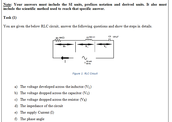
You are given the below RLC circuit, answer the following questions and show the steps in details.
и350 mH
с1 120 иF
R1 3002
VR
50 volt
60 Hz
Figure 1: RLC Circuit
a) The voltage developed across the inductor (VL)
b) The voltage dropped across the capacitor (Vc)
c) The voltage dropped across the resistor (VR)
d) The impedance of the circuit
e) The supply Current (I)
f) The phase angle
Expert Solution
This question has been solved!
Explore an expertly crafted, step-by-step solution for a thorough understanding of key concepts.

This is a popular solution!

Trending now
This is a popular solution!

Step by step
Solved in 3 steps with 3 images
