A combinational logic circuit has one output (F) and four inputs (a, b, نقطة واحدة c, and d). The circuit is described by the following Boolean expression. A static one hazard occurs when F = (a +b + €)(a + c + d)(5 +c +d)(ã +ē + d) abcd=1111 changed to 1001 O abcd%3D0001 changed to 1010 abcd=1101 changed to 1111 abcd31010 changed to 0000 abcd=1011 changed to 1101 abcd=0010 changed to 0000 abcd=D0000 changed to 0010 O
A combinational logic circuit has one output (F) and four inputs (a, b, نقطة واحدة c, and d). The circuit is described by the following Boolean expression. A static one hazard occurs when F = (a +b + €)(a + c + d)(5 +c +d)(ã +ē + d) abcd=1111 changed to 1001 O abcd%3D0001 changed to 1010 abcd=1101 changed to 1111 abcd31010 changed to 0000 abcd=1011 changed to 1101 abcd=0010 changed to 0000 abcd=D0000 changed to 0010 O

Programming Logic & Design Comprehensive
9th Edition
ISBN:9781337669405
Author:FARRELL
Publisher:FARRELL
Chapter4: Making Decisions
Section: Chapter Questions
Problem 4RQ

Related questions
Question
I need the answer as soon as possible
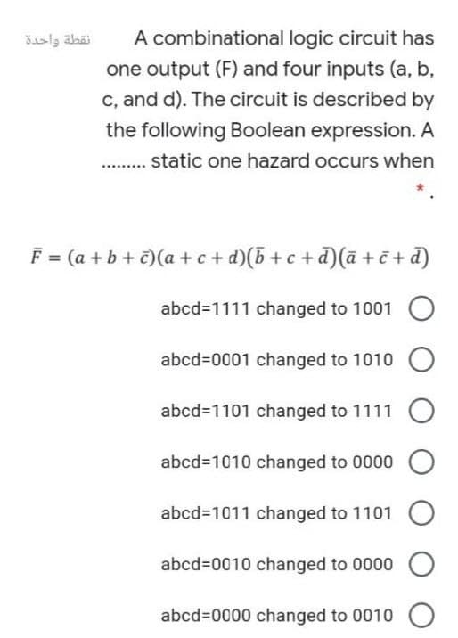
Transcribed Image Text:نقطة واحدة
A combinational logic circuit has
one output (F) and four inputs (a, b,
c, and d). The circuit is described by
the following Boolean expression. A
static one hazard occurs when
F = (a +b + c)(a + c+ d)(5 + c +d)(ā + č + d)
abcd31111 changed to 1001
abcd%3D0001 changed to 1010
abcd31101 changed to 1111
abcd3D1010 changed to 0000
abcd=1011 changed to 1101
abcd=0010 changed to 0000
abcd%3D0000 changed to 0010
Expert Solution
This question has been solved!
Explore an expertly crafted, step-by-step solution for a thorough understanding of key concepts.

Step by step
Solved in 2 steps

Knowledge Booster


Learn more about
Need a deep-dive on the concept behind this application? Look no further. Learn more about this topic, computer-science and related others by exploring similar questions and additional content below.Recommended textbooks for you
Programming Logic & Design Comprehensive
Computer Science
ISBN:
9781337669405
Author:
FARRELL
Publisher:
Cengage
Programming Logic & Design Comprehensive
Computer Science
ISBN:
9781337669405
Author:
FARRELL
Publisher:
Cengage