o determine the state of stress in a solid rod using the principle of superposition. A solid rod has a diameter of e = 50 mm and is subjected to the loading shown. Let a = 190 mm, b= 220 mm, c = 310 mm, d = 220 mm, and P = 3.0 kN. Take point A to be at the top of the circular cross-section. (Figure 1) Figure < 1 of 2 ▼ ▼ Part A - Moment about the x axis at A M₂ = As shown (Figure 2), a cut was made at A to determine the resultant internal loadings. Determine the moment about the x axis, M, Express your answer to three significant figures and include the appropriate units
o determine the state of stress in a solid rod using the principle of superposition. A solid rod has a diameter of e = 50 mm and is subjected to the loading shown. Let a = 190 mm, b= 220 mm, c = 310 mm, d = 220 mm, and P = 3.0 kN. Take point A to be at the top of the circular cross-section. (Figure 1) Figure < 1 of 2 ▼ ▼ Part A - Moment about the x axis at A M₂ = As shown (Figure 2), a cut was made at A to determine the resultant internal loadings. Determine the moment about the x axis, M, Express your answer to three significant figures and include the appropriate units

Principles of Foundation Engineering (MindTap Course List)
8th Edition
ISBN:9781305081550
Author:Braja M. Das
Publisher:Braja M. Das
Chapter6: Vertical Stress Increase In Soil
Section: Chapter Questions
Problem 6.4P: Refer to Figure P6.4. A strip load of q = 900 lb/ft2 is applied over a width B = 36 ft. Determine...

Related questions
Question
To determine the state of stress in a solid rod using the principle of superposition.
A solid rod has a diameter of e = 50 mm and is subjected to the loading shown. Let a = 190 mm, b= 220 mm, c = 310 mm, d = 220 mm, and P = 3.0 kN. Take point A
to be at the top of the circular cross-section. (Figure 1)
Figure
< 1 of 2
▼
▼
Part A - Moment about the x axis at A
M₂ =
As shown (Figure 2), a cut was made at A to determine the resultant internal loadings. Determine the moment about the x axis, M,
Express your answer to three significant figures and include the appropriate units
Transcribed Image Text:State of Stress Caused by Combined Loadings
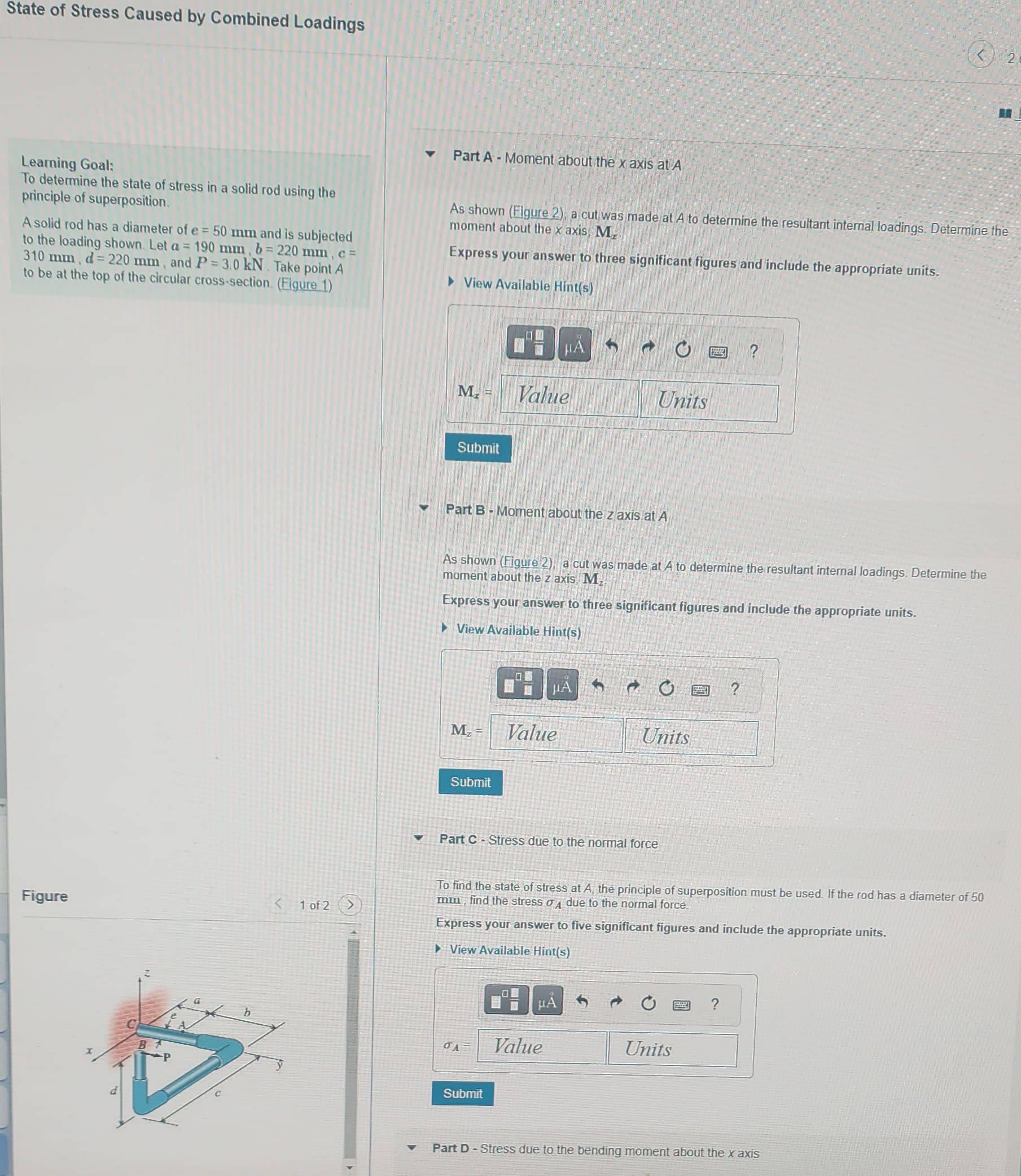
Learning Goal:
To determine the state of stress in a solid rod using the
principle of superposition.
A solid rod has a diameter of e = 50 mm and is subjected
to the loading shown. Let a = 190 mm, b= 220 mm, c =
310 mm, d = 220 mm, and P = 3.0 kN. Take point A
to be at the top of the circular cross-section (Figure 1)
Figure
b
<
1 of 2
▼
▼
Part A Moment about the x axis at A
As shown (Figure 2), a cut was made at A to determine the resultant internal loadings. Determine the
moment about the x axis, Mr.
Express your answer to three significant figures and include the appropriate units.
► View Available Hint(s)
M₂
Submit
M₂ =
Part B - Moment about the z axis at A
Submit
00
Value
As shown (Figure 2), a cut was made at A to determine the resultant internal loadings. Determine the
moment about the z axis, M₂
Express your answer to three significant figures and include the appropriate units.
► View Available Hint(s)
OA=
0
Submit
HÅ
Value
Units
Part C-Stress due to the normal force
→
μÅ
Value
Units
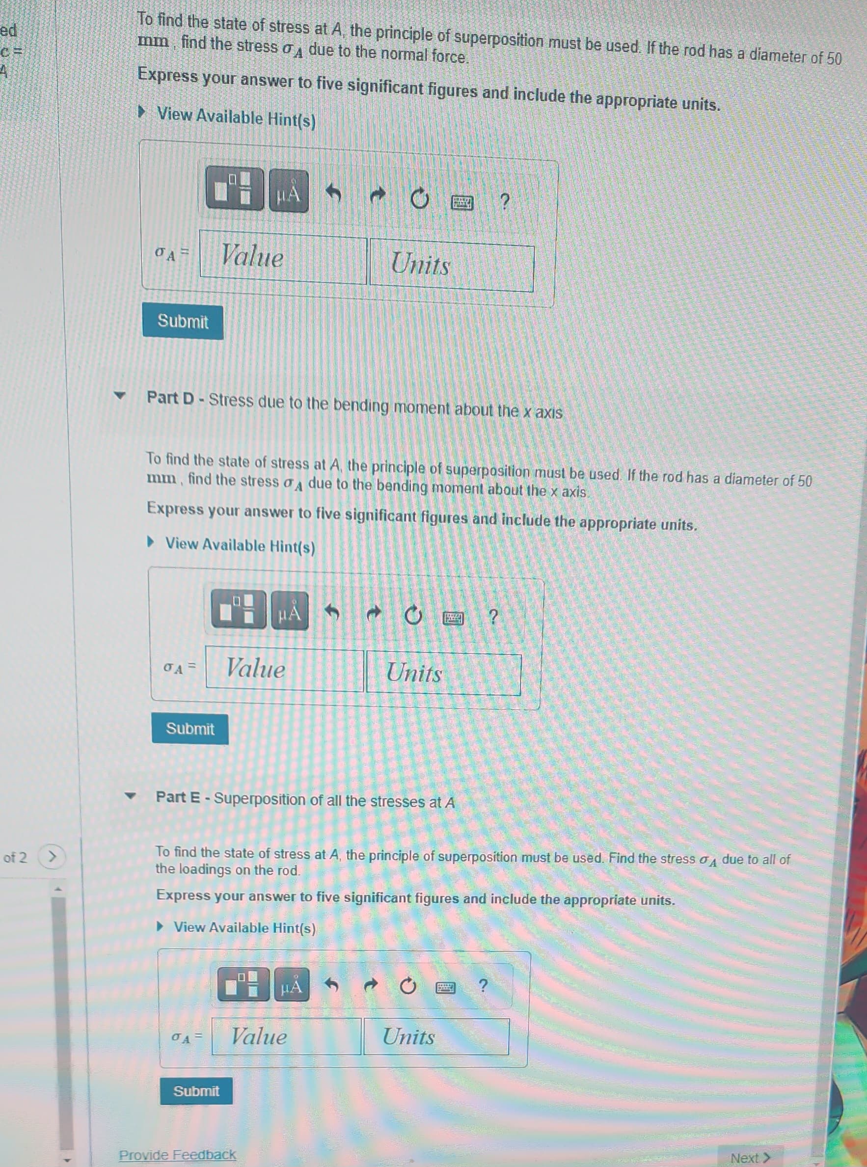
To find the state of stress at A, the principle of superposition must be used. If the rod has a diameter of 50
mm, find the stress A due to the normal force.
Express your answer to five significant figures and include the appropriate units.
►View Available Hint(s)
542
B
Units
?
?
2
Part D-Stress due to the bending moment about the x axis
Transcribed Image Text:c=
of 2
▼
To find the state of stress at A, the principle of superposition must be used. If the rod has a diameter of 50
mm, find the stress σ due to the normal force.
Express your answer to five significant figures and include the appropriate units.
View Available Hint(s)
Submit
PH
Value
Submit
μA
OA= Value
0A =
Part D-Stress due to the bending moment about the x axis
To find the state of stress at A, the principle of superposition must be used. If the rod has a diameter of 50
mm, find the stress A due to the bending moment about the x axis
Express your answer to five significant figures and include the appropriate units.
► View Available Hint(s)
HA
Submit
f
Provide Feedback
O
Units
▾ Part E - Superposition of all the stresses at A
HA
Value
To find the state of stress at A, the principle of superposition must be used. Find the stress o due to all of
the loadings on the rod.
Express your answer to five significant figures and include the appropriate units.
View Available Hint(s)
S
O?
Units
?
Units
Next >
5641
Expert Solution
This question has been solved!
Explore an expertly crafted, step-by-step solution for a thorough understanding of key concepts.
Step 1: Determine the given data.
VIEWStep 2: (a) Determine the bending moment about x-axis.
VIEWStep 3: (b) Determine the bending moment about z-axis.
VIEWStep 4: (c) Determine the stress due to normal force.
VIEWStep 5: (d) Determine the stress due to bending moment.
VIEWStep 6: (e) Determine the total stress.
VIEWSolution
VIEW
Step by step
Solved in 7 steps with 15 images

Knowledge Booster


Learn more about
Need a deep-dive on the concept behind this application? Look no further. Learn more about this topic, civil-engineering and related others by exploring similar questions and additional content below.Recommended textbooks for you
Principles of Foundation Engineering (MindTap Cou…
Civil Engineering
ISBN:
9781305081550
Author:
Braja M. Das
Publisher:
Cengage Learning
Principles of Foundation Engineering (MindTap Cou…
Civil Engineering
ISBN:
9781305081550
Author:
Braja M. Das
Publisher:
Cengage Learning