O O Lin Figure -1 10in For the Section shown in the Figure-1 above, Compute connection capacity for the Bolts 7/8 inch in diameter Type A325 where the threads are excluded from shear plane and the deformation around bolts holes is design consideration
O O Lin Figure -1 10in For the Section shown in the Figure-1 above, Compute connection capacity for the Bolts 7/8 inch in diameter Type A325 where the threads are excluded from shear plane and the deformation around bolts holes is design consideration

Steel Design (Activate Learning with these NEW titles from Engineering!)
6th Edition
ISBN:9781337094740
Author:Segui, William T.
Publisher:Segui, William T.
Chapter3: Tension Members
Section: Chapter Questions
Problem 3.5.3P

Related questions

Question
I need the answer quickly
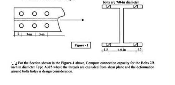
Transcribed Image Text:bolts are 7/8-in diameter
O O
O o o
2 lin l-in
Figure -1
10-in
For the Section shown in the Figure-l above, Compute connection capacity for the Bolts 7/8
inch in diameter Type A325 where the threads are excluded from shear plane and the deformation
around bolts holes is design consideration
Expert Solution
This question has been solved!
Explore an expertly crafted, step-by-step solution for a thorough understanding of key concepts.

Step by step
Solved in 2 steps

Knowledge Booster


Learn more about
Need a deep-dive on the concept behind this application? Look no further. Learn more about this topic, civil-engineering and related others by exploring similar questions and additional content below.Recommended textbooks for you
Steel Design (Activate Learning with these NEW ti…
Civil Engineering
ISBN:
9781337094740
Author:
Segui, William T.
Publisher:
Cengage Learning
Steel Design (Activate Learning with these NEW ti…
Civil Engineering
ISBN:
9781337094740
Author:
Segui, William T.
Publisher:
Cengage Learning