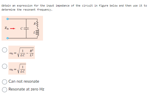
Obtain an expression for the input impedance of the circuit in figure below and then use it to determine the resonant frequency.
Obtain an expression for the input impedance of the circuit in figure below and then use it to determine the resonant frequency.

Delmar's Standard Textbook Of Electricity
7th Edition
ISBN:9781337900348
Author:Stephen L. Herman
Publisher:Stephen L. Herman
Chapter24: Resistive-inductive-capacitive Parallel Circuits
Section: Chapter Questions
Problem 4RQ: A tank circuit contains a capacitor and an inductor that produce 30 of reactance at the resonant...

Related questions
Question
100%
Obtain an expression for the input impedance of the circuit in figure below and then use it to
determine the resonant frequency.
Transcribed Image Text:obtain an expression for the input impedance of the circuit in figure below and then use it to
determine the resonant frequency.
Zin
w0 =
00
1 R²
VLC 1.²
LC
B
elem
Can not resonate
Resonate at zero Hz
Expert Solution
This question has been solved!
Explore an expertly crafted, step-by-step solution for a thorough understanding of key concepts.

This is a popular solution!

Trending now
This is a popular solution!

Step by step
Solved in 4 steps with 5 images

Knowledge Booster


Learn more about
Need a deep-dive on the concept behind this application? Look no further. Learn more about this topic, electrical-engineering and related others by exploring similar questions and additional content below.Recommended textbooks for you
Delmar's Standard Textbook Of Electricity
Electrical Engineering
ISBN:
9781337900348
Author:
Stephen L. Herman
Publisher:
Cengage Learning
Delmar's Standard Textbook Of Electricity
Electrical Engineering
ISBN:
9781337900348
Author:
Stephen L. Herman
Publisher:
Cengage Learning