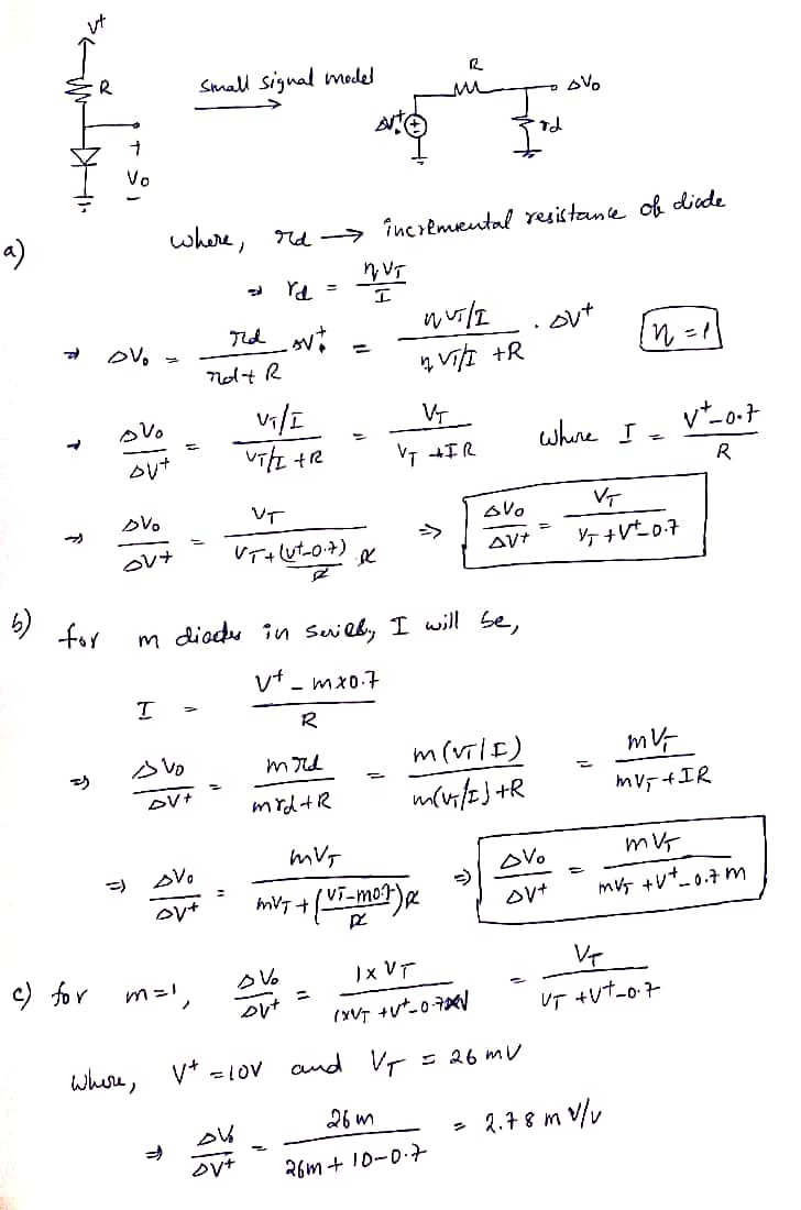
oftage-regulator circuit shown in Fig. P4.57. The value of R IS selected to obtain an output voltage Vo (across the diode) of 0.7 V. V+ Vo Figure P4.57 (a) Use the diode small-signal model to show that the change in output voltage corresponding to a change of 1 V in V* is AV AV+ V, V+ +V, – 0.7 This quantity is known as the line regulation and is usually expressed in mV/V. (b) Generalize the expression above for the case of m diodes connected in series and the value of R adjusted so that the voltage across each diode is 0.7 V (and Vo=0.7m V). (c) Calculate the value of line regulation for the case V = 10 V (nominally) and (i) m = 1 and (ii) m = 3.
oftage-regulator circuit shown in Fig. P4.57. The value of R IS selected to obtain an output voltage Vo (across the diode) of 0.7 V. V+ Vo Figure P4.57 (a) Use the diode small-signal model to show that the change in output voltage corresponding to a change of 1 V in V* is AV AV+ V, V+ +V, – 0.7 This quantity is known as the line regulation and is usually expressed in mV/V. (b) Generalize the expression above for the case of m diodes connected in series and the value of R adjusted so that the voltage across each diode is 0.7 V (and Vo=0.7m V). (c) Calculate the value of line regulation for the case V = 10 V (nominally) and (i) m = 1 and (ii) m = 3.

Introductory Circuit Analysis (13th Edition)
13th Edition
ISBN:9780133923605
Author:Robert L. Boylestad
Publisher:Robert L. Boylestad
Chapter1: Introduction
Section: Chapter Questions
Problem 1P: Visit your local library (at school or home) and describe the extent to which it provides literature...

Related questions
Question
100%
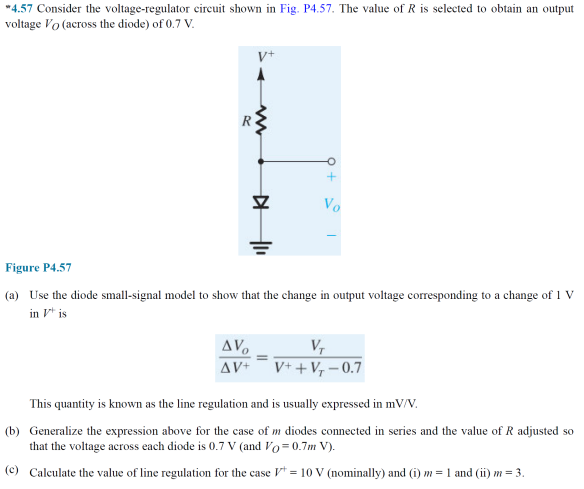
Transcribed Image Text:"4.57 Consider the voltage-regulator circuit shown in Fig. P4.57. The value of R is selected to obtain an output
voltage Vo (across the diode) of 0.7 V.
Vo
Figure P4.57
(a) Use the diode small-signal model to show that the change in output voltage corresponding to a change of 1 V
in V* is
AV.
V,
V+ + V, – 0.7
AV+
This quantity is known as the line regulation and is usually expressed in mV/V.
(b) Generalize the expression above for the case of m diodes connected in series and the value of R adjusted so
that the voltage across each diode is 0.7 v (and Vo=0.7m V).
(c) Caleulate the value of line regulation for the case V = 10 V (nominally) and (i) m = 1 and (ii) m = 3.
Expert Solution
Step 1

Trending now
This is a popular solution!

Step by step
Solved in 2 steps with 2 images

Knowledge Booster


Learn more about
Need a deep-dive on the concept behind this application? Look no further. Learn more about this topic, electrical-engineering and related others by exploring similar questions and additional content below.Recommended textbooks for you
Introductory Circuit Analysis (13th Edition)
Electrical Engineering
ISBN:
9780133923605
Author:
Robert L. Boylestad
Publisher:
PEARSON

Delmar's Standard Textbook Of Electricity
Electrical Engineering
ISBN:
9781337900348
Author:
Stephen L. Herman
Publisher:
Cengage Learning

Programmable Logic Controllers
Electrical Engineering
ISBN:
9780073373843
Author:
Frank D. Petruzella
Publisher:
McGraw-Hill Education
Introductory Circuit Analysis (13th Edition)
Electrical Engineering
ISBN:
9780133923605
Author:
Robert L. Boylestad
Publisher:
PEARSON
Delmar's Standard Textbook Of Electricity
Electrical Engineering
ISBN:
9781337900348
Author:
Stephen L. Herman
Publisher:
Cengage Learning
Programmable Logic Controllers
Electrical Engineering
ISBN:
9780073373843
Author:
Frank D. Petruzella
Publisher:
McGraw-Hill Education

Fundamentals of Electric Circuits
Electrical Engineering
ISBN:
9780078028229
Author:
Charles K Alexander, Matthew Sadiku
Publisher:
McGraw-Hill Education

Electric Circuits. (11th Edition)
Electrical Engineering
ISBN:
9780134746968
Author:
James W. Nilsson, Susan Riedel
Publisher:
PEARSON

Engineering Electromagnetics
Electrical Engineering
ISBN:
9780078028151
Author:
Hayt, William H. (william Hart), Jr, BUCK, John A.
Publisher:
Mcgraw-hill Education,