or the lag circuit in Figure 3, determine the phase lag of the output voltage with respect to the input for the owing frequencies: 1 Hz (b) 100 Hz (c) 1 kHz (d) 10 kHz Vin IV L m 10 H R 39 ΚΩ Figura 2 Vout
or the lag circuit in Figure 3, determine the phase lag of the output voltage with respect to the input for the owing frequencies: 1 Hz (b) 100 Hz (c) 1 kHz (d) 10 kHz Vin IV L m 10 H R 39 ΚΩ Figura 2 Vout

Delmar's Standard Textbook Of Electricity
7th Edition
ISBN:9781337900348
Author:Stephen L. Herman
Publisher:Stephen L. Herman
Chapter24: Resistive-inductive-capacitive Parallel Circuits
Section: Chapter Questions
Problem 3PP: The circuit in Figure 24-2 is connected to a 60-Hz line. The apparent power in the circuit is 48.106...

Related questions
Question
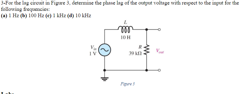
Transcribed Image Text:3-For the lag circuit in Figure 3, determine the phase lag of the output voltage with respect to the input for the
following frequencies:
(a) 1 Hz (b) 100 Hz (c) 1 kHz (d) 10 kHz
Vin
IV
L
m
10 H
R
39 ΚΩ
Figure 3
www
Vout
Expert Solution
This question has been solved!
Explore an expertly crafted, step-by-step solution for a thorough understanding of key concepts.

Step by step
Solved in 7 steps with 12 images

Knowledge Booster


Learn more about
Need a deep-dive on the concept behind this application? Look no further. Learn more about this topic, electrical-engineering and related others by exploring similar questions and additional content below.Recommended textbooks for you
Delmar's Standard Textbook Of Electricity
Electrical Engineering
ISBN:
9781337900348
Author:
Stephen L. Herman
Publisher:
Cengage Learning
Delmar's Standard Textbook Of Electricity
Electrical Engineering
ISBN:
9781337900348
Author:
Stephen L. Herman
Publisher:
Cengage Learning