Oscilloscope The oscilloscope is an instrument that will display the variation of a voltage with time on a flat screen monitor. The vertical axis is scaled off in volts while the horizontal axis is in units of time. The number of vertical and horizontal divisions on the screen is not fixed, but the majority have eight vertical divisions and 10 horizontal divisions. The basic components of an oscilloscope appear in Fig. 2.1. The signal of interest is applied to the vertical input. Depending on its strength, it may be reduced in level (attenuated) or increased in level (amplified). The horizontal input permits applying another signal of any
Oscilloscope The oscilloscope is an instrument that will display the variation of a voltage with time on a flat screen monitor. The vertical axis is scaled off in volts while the horizontal axis is in units of time. The number of vertical and horizontal divisions on the screen is not fixed, but the majority have eight vertical divisions and 10 horizontal divisions. The basic components of an oscilloscope appear in Fig. 2.1. The signal of interest is applied to the vertical input. Depending on its strength, it may be reduced in level (attenuated) or increased in level (amplified). The horizontal input permits applying another signal of any

Introductory Circuit Analysis (13th Edition)
13th Edition
ISBN:9780133923605
Author:Robert L. Boylestad
Publisher:Robert L. Boylestad
Chapter1: Introduction
Section: Chapter Questions
Problem 1P: Visit your local library (at school or home) and describe the extent to which it provides literature...

Related questions

Question
I need help to understand what does oscilloscope is about in background theory.
Transcribed Image Text:kind to interact with the vertical input to produce a waveform that can often be quite informa-
tive. However, if you simply want to view the signal applied to the vertical input versus time,
then the sync input option is selected. The sweep oscillator will then generate a sawtooth wave-
form, such as in Fig. 2.1, to move the applied signal across the screen. If the frequency of the
applied signal and that of the sawtooth waveform are the same, the waveforms, are said to be "in
syne" and the desired signal will sit stable on the screen. If the two frequencies do not match,
the waveform will appear to be continually moving horizontally. Fortunately, all scopes have a
sweep time control to adjust the frequency of the sawtooth waveform so a steady image can be
displayed.
Note in Fig. 2.1 that the voltage of a sawtooth waveform increases linearly
(straight line) with time. This is to ensure that the applied signal will appear across the full
width of the screen in an undistorted manner. For the case of an applied sinusoidal voltage,
the voltage between the two input terminals will increase and decrease in an oscillatory
manner. In the absence of the sawtooth waveform at the horizontal input, the waveform on the
screen would simply be a vertical line with a high intensity spot moving up and down on
the screen with the same frequency as the applied signal. Applying the sawtooth voltage to the
horizontal input will move the waveform across the screen so the full sinusoidal pattern can
be displayed.
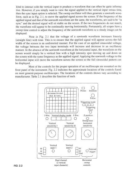
Most of the controls for the proper operation of an oscilloscope are mounted on the
front panel of the instrument. Fig. 2.2 indicates the approximate locations of the controls found
on most general-purpose oscilloscopes. The locations of the controls shown vary according to
manufacturer. Table 2.1 describes the function of each.
FIG. 2.2
Power Intensity
divisions (in cm)
(hor. & vert.)
Fucus
Triggering mode
Triggering
level
y-Pos. Vertical display mode Y-Pos.
X-position
Sweep time
Vertical
sensitivity I
Vertical
sensitivity II
horizontal
sensitivity
Vertical
input1
Vertical
input 2
de
External
○
trigger
Gnd
God
Dual channel
12 vertical
input channels)
Horizontal
sweep
controls
Transcribed Image Text:RÉSUMÉ OF THEORY
Oscilloscope
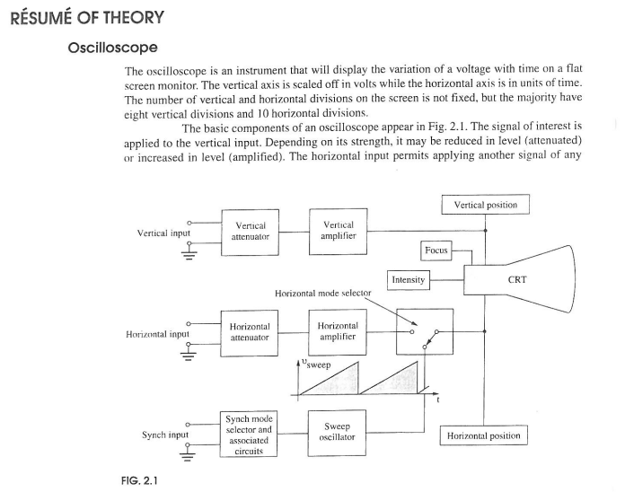
The oscilloscope is an instrument that will display the variation of a voltage with time on a flat
screen monitor. The vertical axis is scaled off in volts while the horizontal axis is in units of time.
The number of vertical and horizontal divisions on the screen is not fixed, but the majority have
eight vertical divisions and 10 horizontal divisions.
The basic components of an oscilloscope appear in Fig. 2.1. The signal of interest is
applied to the vertical input. Depending on its strength, it may be reduced in level (attenuated)
or increased in level (amplified). The horizontal input permits applying another signal of any
Vertical input
Vertical
attenuator
Vertical
amplifier
Intensity
Horizontal mode selector
Horizontal input
Horizontal
attenuator
Horizontal
amplifier
"sweep
Synch input
FIG. 2.1
Focus
Vertical position
CRT
Synch mode
selector and
associated
circuits
Sweep
oscillator
Horizontal position
Expert Solution
This question has been solved!
Explore an expertly crafted, step-by-step solution for a thorough understanding of key concepts.

Step by step
Solved in 4 steps

Knowledge Booster


Learn more about
Need a deep-dive on the concept behind this application? Look no further. Learn more about this topic, electrical-engineering and related others by exploring similar questions and additional content below.Recommended textbooks for you
Introductory Circuit Analysis (13th Edition)
Electrical Engineering
ISBN:
9780133923605
Author:
Robert L. Boylestad
Publisher:
PEARSON

Delmar's Standard Textbook Of Electricity
Electrical Engineering
ISBN:
9781337900348
Author:
Stephen L. Herman
Publisher:
Cengage Learning

Programmable Logic Controllers
Electrical Engineering
ISBN:
9780073373843
Author:
Frank D. Petruzella
Publisher:
McGraw-Hill Education
Introductory Circuit Analysis (13th Edition)
Electrical Engineering
ISBN:
9780133923605
Author:
Robert L. Boylestad
Publisher:
PEARSON
Delmar's Standard Textbook Of Electricity
Electrical Engineering
ISBN:
9781337900348
Author:
Stephen L. Herman
Publisher:
Cengage Learning
Programmable Logic Controllers
Electrical Engineering
ISBN:
9780073373843
Author:
Frank D. Petruzella
Publisher:
McGraw-Hill Education

Fundamentals of Electric Circuits
Electrical Engineering
ISBN:
9780078028229
Author:
Charles K Alexander, Matthew Sadiku
Publisher:
McGraw-Hill Education

Electric Circuits. (11th Edition)
Electrical Engineering
ISBN:
9780134746968
Author:
James W. Nilsson, Susan Riedel
Publisher:
PEARSON

Engineering Electromagnetics
Electrical Engineering
ISBN:
9780078028151
Author:
Hayt, William H. (william Hart), Jr, BUCK, John A.
Publisher:
Mcgraw-hill Education,