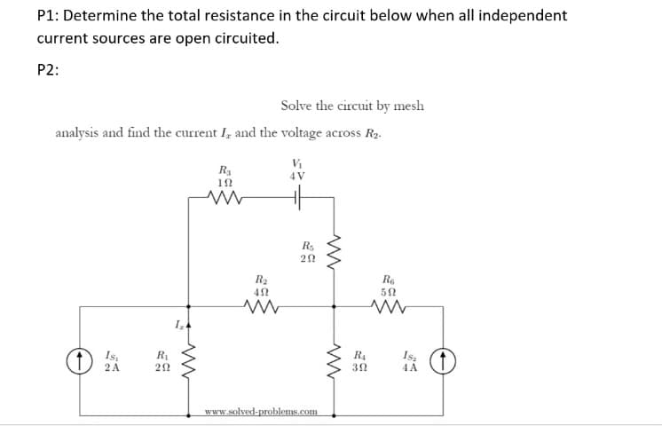
P1: Determine the total resistance in the circuit below when all independent current sources are open circuited. P2: Solve the circuit by mesh


Q: 1. Find the mesh currents for the circuit shown and the voltage across the resistances.
A:
Q: For the circuit below, find vı & v2. 90 Ω 60 N 150 N V1 {75 N 3 V V2§ 30 N 40 N
A:
Q: Given the following circuit, solve for R1, and the gain of the current source. Given: A 20V source…
A: In this question circuit is given....We have to find out unknown resistance value and gain of…
Q: Find the equivalent resistence that is seen by the 20 V source in the circuit shown to the right,…
A: The equivalent resistance is calculated by start reducing from left to right by taking series and…
Q: Q2) For the circuit shown, Find I, V, V, and the power dissipated in R.? E,+ 18V R sa E- -6 V Ry R4
A: First we will find current in all branches and than voltages using ohms law. power dissipated=V2R.
Q: For the circuit shown below, find the current in the 8 ohm resistance if R,-6, R2 =8 and V =98volts.…
A: First we will find source current ,using current division rule we will find current in 8 ohm…
Q: Use mesh-current analysis to find the value of v in the circuit of Figure P2.38.
A: Given data, The value of resistance R1 = 20 Ω The value of resistance R2 = 20 Ω The value of…
Q: Obtain the equivalent resistance REQ for the circuit below and use it to find current i. Shown your…
A:
Q: Q3)For the circuit shown below determine the value of current (I) through the resistance R=2N if…
A:
Q: Q2)Solve the following problem In the network shown in figure below, find the value of RL such that…
A: In this question we need to find maximum power and load resistance for transfer maximum power to…
Q: the heat of Vs, such that the power dissipated in the 4 ohm resistor is 64 watts, it is kno
A: Mesh analysis is a combination of KCL and Ohm's law. It is applicable for a linear system.
Q: Find the current IO and voltage V1 in the circuit shown below using the techniques of equivalent…
A:
Q: 2. For the circuit shown below: a) Use mesh-current method to find V2, V2, and i,. b) How much power…
A:
Q: Use Norton’s theorem to determine the current flowing in the 3-ohm resistance of the network shown…
A:
Q: The circuit in figure 1 consist of components Vs, R1, R2 and R3. Find the expression for the power…
A:
Q: Use voltage and current division to find V1, V2, I2, and I3 in the circuit shown, if V = 1 V, R1 =24…
A: GIVEN: V = 1 V, R1 =24 kΩ, R2 =30 kΩ R3 =11 kΩ Find Equivalent, Req=R1 + R2||R3Req=24+ 30||11Req=24+…
Q: В |C D The branch currents h, 2, 3, and l4 are А, A, A, and |A, respectively.
A: The given circuit with proper markings can be drawn as: According to KCL Sum of incoming…
Q: Find the worst-case values of V1, I2, and I3 for the circuit shown if the resistor tolerances are 10…
A: Here in this problem the worst case values means the values which are calculated on the tolerance…
Q: Q3)For the circuit shown below determine the value of current (I) through the resistance R=22 .if…
A:
Q: In the circuit shown, find V2, I3, I2, l1, and V1 . R2 1 kN R, R3 3 kN 5 mA ↑ V, V2 RA 4.5 kN 6 kN
A: This question belongs to circuit theory . It is based on the concept of kirchhoff's current law . It…
Q: R =20 E 20 V R2 V2 Rr R=5 12 - V, +
A: According to the question we have to find the value of Total resistance, Current Source, Value of…
Q: Given the circuit shown below. Assume that all resistor have a resistance of R (a) If a voltage Vs…
A:
Q: Calculate the current flowing through the R2 resistor in the circuit shown in the figure by the…
A: According to super position theorem current through R2 can be found by adding algebraically the…
Q: Use voltage and current division to find V1, V2, I2, and I3 in the circuit shown if V = 8 V, R1 =30…
A: Find Req Req=30+24||15Req=30+24×1524+15Req=30+24×1524+15Req=39.23 kΩ find current; i=839.23i=0.2039…
Q: Design a circuit that will have an outcome of the highest equivalent resistance across the terminals…
A:
Q: Q/ For the circuit shown below, find the following: 1- Voltage drop across the resistance 122 by…
A: In the circuit, resistance and battery consist. Find the voltage across 12 ohm resistance and…
Q: 1. In the circuit shown below, the total power dissipated by the circuit is 500W. The power…
A: Note: According to Q&A policy, we are allowed to answer only 3 subparts in multiple subparts…
Q: Find the Norton equivalent circuit for the network in the shaded area of the network of figure…
A: Given Find the Norton Equivalent circuit and calculate current through R4.
Q: Consider the circuit below in which the dependent current source depends on the current it, the…
A: The given circuit diagram is shown below: It is given that: IO=90 mA=90×10-3 Ai1=15 mA=15×10-3…
Q: Exercise 2 In the circuit shown, use Kirchhoff's voltage law to find the voltage (V,) and current in…
A:
Q: Consider the circuit shown below. The source voltage V1 is 45 V. Resistance R1, R2 and R3 are 4…
A: We will find out output voltage by using of krichoff's current law
Q: From the given circuit, find I, the power dissipated by the resistor, and the power supplied by each…
A: Perform the following steps to get the required answers: 1. Apply the KVL in the given close loop to…
Q: R3 R2 R1 U R4 R5 Voltage U and all resistances R are known. Notice all currents in the circuit.…
A:
Q: For the circuit find voltages v, and v2. www 20 V
A: KVL (Kirchhoff's Voltage Law) states that the algebraic sum of all voltage in a closed loop is zero.…
Q: Given the circuit below: If R1 = 3 Ω, R2 = 7 Ω, R3 = 5 Ω, V1 = 8 V, V2 = 4 V, and V3 = 6 V, what is…
A: In this question we need to find a current through R2 resistance.
Q: For the circuit shown in the figure, obtain the current in resistor R if its resistance is 20Ω.…
A:
Q: Determine the equivalent resistance between the terminals a and be in the circuit shown below.
A:
Q: Consider the circuit shown below. What is the value of voltage V2? V1 = 28 V R1 2 A R2 = 3 Q 12 V2…
A:
Q: Consider the following figure with V = 120 V with an internal resistance Rs of 50 ohms supplying a…
A: Given: V=120 V RS=50 ohm for maximum power transfer theorem, load resistance must be equal to…
Q: Find the equivalent resistance seen by the source, the currents I1, I2, I3, I4, I5, I6 and the…
A: Given:
Q: Find V, for the circuit given below. 40 k2 o vo o ww 20 k2 v, = 6 V, v, =?
A:
Q: For the circuit shown find V1, and V2. 2 A V2 V1 10 Ω 20 2 4 A
A: In the circuit, it can be seen that the voltage V2 is 0 Volt because it is directly connected to the…
Q: For the resistor network shown below, write a MATLAB code to calculate the total resistance seen by…
A:
Q: Consider the circuit shown in below Figure, Find values of the resistances R1 and R2 that cause the…
A:
Q: For the circuit in the given figure, V2(s)/V1(s) %3D R V1 V2
A:
Q: Example: Find the current I, in the network in Figure below. 6 k2 ww 2V 12 k2 V2 12 k2 6 kn V +)6V…
A: The given circuit is,
Q: Find the total resistance of the circuit shown below. V R2 500k R3 R1 1M R4 1M 125V |250k
A: In this question , we have to find out equivalent resistance of circuit..
Q: The current flowing in resistor R in the circuit shown in figure is l,+ l2. A R r2 E1 E2 D C Select…
A:
Q: R4 R2 R1
A:
Please answer it with complete solutions. Thanks

Step by step
Solved in 4 steps with 3 images

- In an R-L parallel circuit, ET=208 volts, R=2.4k, and XL=1.8k. Find IT.Using Kirchhoff's Rules, compute the current (mA) and voltage (V) values of the circuit if R1=2kΩ and R2=7kΩ.Find the equivalent resistance Rab (in ohms) of the circuit shown by using a Wye-to-Delta transformation involving resistors R2, R3, and R5. After transforming R2, R3, and R5 from wye connection to delta connection, what are the values of the resistances (in ohms) of the resulting delta connection? List them in any order below.
- Question: In the circuit to the right, R1 = R2,W/L = 3, Vtn = 0.6 V, and Kn = 200 A/V2. Determine the values of R1 and R2 such that VD = 1 V and Vs = -1 V.Circuit Analysis , answer the questions below for the given circuit in the picture. Thanks. V1=7V, R1=6 Ω, R2=8 Ω, R3=5 Ω, R4=5 Ω and I1=11 A i1=? PV1 =? PI1 =? P5i1 =?For the number 1 question, you have to find the thevenin equivalent resistance at the load terminals and also the maximum power transfer to the load. I have posted this question but both gave me different answers, what is the real answer for this? LINK FOR ANSWER 1: https://www.bartleby.com/questions-and-answers/1.-find-the-a-equivalent-thevenin-resistance-at-the-load-terminals-and-b-maximum-power-transfer-to-t/bb07ad30-0e58-4e87-a919-c3846bad184bLINK FOR ANSWER 2: https://www.bartleby.com/questions-and-answers/1.-determine-the-equivalent-thevenin-resistance-at-the-load-terminals-and-maximum-power-transfer-to-/eded9e03-db33-44c9-b6f7-c9616cbaab35 Also, kindly check if the answers to question number 2 on the links are correct.
- After transforming R2, R3, and R5 from wye connection to delta connection, what are the values of the resistances (in ohms) of the resulting delta connection? List them in any order belowDetermine r2 using product/sum rule. RT=40 ohms R1=200 ohms R2=? Solve using this equation "RT=(R1 X R2)/(R1+R2)" Also its a parallel circuit1) Using only source transformation and without eliminating vx, reduce the circuit in Figure until you get a single current source and a single resistor, then obtain vx using Ohm's law. What is the value of the current source in A? 2) What is the value of the resistance in Ω? 3)What is the value of Vx in Volts? 4)For the circuit in Figure, set up the supernode equation: Response format: Ava±Bvb±Cvx=D 5)For the circuit in Figure, set up the auxiliary equation for the supernode: Response format: Ava±Bvb±Cvx=D 6)For the circuit in Figure, set up the equation of the remaining node: Response format: Ava±Bvb±Cvx=D
- Since R1=9282.13ohm, R2=3403.87ohm and Ri=Infinite in the circuit given in the figure, write the equivalent resistance in Ohms between the terminals A-B.Answer the following if V1=8V, R1=9 Ω, R2=3 Ω, R3=4 Ω, R4=7 Ω and I1=10 A in the circuit in the figure i1=? Pv1=? PI1=? P5i1=?If we measure the voltage at the terminals of a two-terminal network with two known (anddifferent) resistive loads attached, we can determine the Thévenin and Norton equivalentcircuits. When a 2.2-kΩ load is attached to a two-terminal circuit, the load voltage is 4.4 V. When the load is increased to 10 kΩ, the load voltage becomes 5 V. Find the Thévenin voltage and resistance for this circuit.