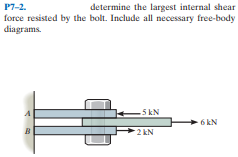
P7-2. determine the largest internal shear force resisted by the bolt. Include all necessary free-body diagrams. 5 kN 6 kN 2 kN


Q: 12-43. The simply supported beam is built up from three boards by nailing them together as shown. If…
A: Given data: The applied force on the beam is p =12 kN. The nail can resist a shear force F =1.5 kN.…
Q: I1-13. Draw the shear and moment diagrams for the beam. м, L/2-
A: Solution : The reaction at the support is calculated as:
Q: 7-11. The overhang beam is subjected to the uniform distributed load having an intensity of w = 50…
A:
Q: F7-3. Determine the internal normal force, shear force, and bending moment at point C in the beam.…
A: Draw the FBD of the given problem. Apply equilibrium condition. Determine the moment about point B.
Q: 7-26. The beam is made from three boards glued together at the seams A and B. If it is subjected to…
A:
Q: F7-15. Determine the maximum average shear stress developed in each 12-mm-diameter bolt. 10 kN 5 kN…
A: Given that →Load=10 KN dia=12 mm=0.012 m
Q: 7-22. Determine the resultant internal loadings acting on the cross section at point E. The load D…
A: Draw the free body diagram for a better understanding of the given problem.
Q: The 800 lb load is being hoisted at a constant speed using the motor M, which has a weight of 90 lb.…
A:
Q: F7-5. Determine the internal normal force, shear force, and bending moment at point Cin the beam. 5…
A: Free body diagram of the beam is given as, On using equilibrium of forces in a horizontal…
Q: P7-6. The single-V butt joint transmits the force of 5 kN from one bar to the other. Determine the…
A: Given data The joint type is: Single-V butt joint Force transfer from the bar: 5 kN Adding the…
Q: F7-2. Determine the internal normal force, shear force, and bending moment at point Cin the beam.…
A: Shear force at any section is the summation of all shear forces acting on either side of that…
Q: *7-4. Determine the resultant internal loadings on the cross section at point D. 1.25 kN/m -1.5 m…
A: The free body diagram of the section ADEB is, Here, P is the effective loading due to the UDL. H…
Q: 12-10. If the applied shear force V= 90 kN, determine the maximum shear stress in the member. 75 mm…
A: The maximum shear stress occurs at the neutral axis (NA). Thus the maximum shear stress in the…
Q: 16-10. Determine the equations of the elastic curve using the coordinates x, and xz What is the…
A:
Q: F7-18. Draw the shear and moment diagrams for the beam. 9 kN/m А 3 m 3 m F7-18
A:
Q: Problem 4 The cable of a suspension bridge supports half of the uniform road surface between the two…
A: The maximum force developed in the cable at the mid point of the cable (L/2) of length L because at…
Q: The turbine develops 300 kW of power, which is transmitted to the gears such that both B and C…
A: Properties: The amount of the torque supplied by the turbine can be determined as,
Q: 3 kip.ft 3 ft A - 6 ft B
A:
Q: The pump operates using the motor that has a power of 85 W. If the impeller at B is turning at 150…
A: Given data as per the question Operating power = 85 w diameter of shaft =20 mm ω = 150 revmin we…
Q: The overhang beam is made of 2014-T6 aluminum. If the 75-kg block has a speed of = 3 m>s at h =…
A: Modulus of elasticity (E) for 2014-T6 aluminium = 72.4 GPa h = 0.75 m v = 3 m/s m = 75 kg L = AB = 4…
Q: B A h
A:
Q: 7-42. If P- 15 kN, determine the average shear stress in the pins at A, B, and C. All pins are in…
A: As per given condition∑Fx=0Ax-FBCcos 30°=0but here FBC not…
Q: 7-21. Determine the resultant internal loadings acting on the cross section at point C in the beam.…
A: Given, The mass of load D, m=300 kg The radius of the pulley, r= 0.1 m Now free body diagram of the…
Q: 7-1. The shaft is supported by a smooth thrust bearing at B and a journal bearing at C. Determine…
A: Free-body diagram of the beam is given as, On considering beam AE, the force equilibrium in a…
Q: The 80-lb weight is dropped from rest at a height h = 4 ft onto the end of the A-36 steel W6 * 12…
A: To find-: The maximum bending stress developed in the beam. Given-: The weight of the body is W=80…
Q: 11-39. The shaft is supported by a smsoth thrust bearing at A and smooth journal bearing at B. Draw…
A: To draw The shear force and moment diagram. Given Concept used The Sum of forces in the vertical…
Q: *7-28. Determine the normal force. shear force, and moment at sections passing through points E and…
A: Given data as per question Moment applied between Point A and E =35 N.m considering FBD of the…
Q: The beam shown has an overall length L of 2 metres. A uniform distributed load of 3.7 kN/m is…
A: In a beam, resisting shear force at any given section can be calculated as sum of all the shear…
Q: R7-6. The bearing pad consists of a 150 mm by 150 mm block of aluminum that supports a compressive…
A: Given data P=6 kNA=150 ×150 mm2=22500 mm2
Q: Determine (approximately) the internal moment and shear at the ends of each member of the portal…
A: Draw the free body diagram for the above problem.
Q: *5-32. The pump operates using the motor that has a power of 85 W. If the impeller at B is turning…
A: Power P=85W Speed N=150rev/min diameter D=20mm To find Maximum shear stress τ
Q: Q1- Determine the normal force Nc, the shear force Vc, and the moment Mc at point C. Assume the beam…
A:
Q: F7-14. The frame supports the loading shown. The pin at A has a diameter of 50 mm. If it is…
A: Free body diagram of the frame is shown in figure. Taking Moments around B, (clockwise positive) PAx…
Q: F7-18. Determine the maximum average shear stress developed in the 30-mm-diameter pin. 30 kN 40 kN
A: Given data: The diameter of pin, dpin = 30 mm. Calculate the resultant force as follows: R=30…
Q: 5-23. If the roller at A and the pin at B can support a load up to 4 kN and 8 kN, respectively,…
A:
Q: Q4. The steel shaft is L mm long and is screwed into the wall using a wrench. Determine the maximum…
A: Given data: The length of the steel rod is L = 380 mm. The magnitude of the couple forces F = 400…
Q: 7-LA Delermine the maximum shear stress in the strut if IL subjocted to a shear force of V= 20 KN.…
A:
Q: *7-48. Draw the shear and moment diagrams for the cantilevered beam. 100 lb 800 lb ft A C В 5 ft 5…
A:
Q: The footing supports the load transmitted by the two columns. Draw the shear and moment diagrams for…
A: The free-body diagram is given as, consider the equilibrium in the y-direction,…
Q: *R7-4. The circular punch B exerts a force of 2 kN on the top of the plate A. Determine the average…
A: Given data: Force exerted by the punch on the plate, P = 2 kN. The diameter of the punch, d = 4 mm.…
Q: *11-20. The smooth pin is supported by two leaves A and B and subjected to a compressive load of 0.4…
A: Draw the diagram of a loaded smooth pin, Apply force equilibrium in a vertical direction and…
Q: F7-5. Determine the internal normal force, shear force, and bending moment at point C in the beam. 5…
A:
Q: •7-1. If the wide-flange beam is subjected to a shear of V = 20 kN, determine the shear stress on…
A: Given Shear stress = 20 kN Find Stress component at the mid point
Q: F7-16. If each of the three nails has a diameter of 4 mm and can withstand an average shear stress…
A: The number of nails in the board is, n=3 Diameter of each nail is, d=4 mm Shear strength of the…
Q: 12-7. The shaft is supported by a thrust bearing at A and a journal bearing at B. IF P = 20 kN,…
A: Given data as per the question Force, P=20 KN
Q: 17-6 The two identical boards are bolled tngether to form the beam. Determine the maximum alowable…
A: Given data:- shear force (V) = 50 kN shear strength of each nail = 15 kN find the spacing of nails.
Q: 7-46. The beam is subjected to a shear of V = 800 N. Determine the average shear stress developed in…
A: Draw the cross section of the given section.
Q: *7-48. Draw the shear and moment diagrans for the beam. 1.5 KN/m 2 m 3 in sp Prob. 7-48
A:
Q: Draw the free-body diagram for the following problem. The crane and boom shown.
A: for the given figure we need to determine its free body diagram
Q: 7-9. Determine the largest shear force Vthat the member can sustain if the allowable shear stres is…
A:


Trending now
This is a popular solution!

Step by step
Solved in 3 steps with 3 images

- The turbine develops 300 kW of power, which is transmitted to the gears such that both B and C receive an equal amount. If the rotation of the 100-mm-diameter A992 steel shaft is v = 600 rev>min., determine the absolute maximum shear stress in the shaft and the rotation of end D of the shaft relative to A. The journal bearing at D allows the shaft to turn freely about its axis.The turbine develops 150 kW of power, which is transmitted to the gears such that both C and D receive an equal amount. If the rotation of the 100-mm-diameter A-36 steel shaft is v = 500 rev>min., determine the absolute maximum shear stress in the shaft and the rotation of end B of the shaft relative to E. The journal bearing at E allows the shaft to turn freely about its axis.7-12 Rod AB is fixed to a smooth collar D, which slides freely along the vertical guide. Determine the normal force, shear force, and moment at point C, which is located just to the left of the 60 lb concentrated load
- When the 100-lb block is at h = 3 ft above the cylindrical post and spring assembly, it has a speed of = 20 ft>s. If the post is made of 2014-T6 aluminum and the spring has the stiffness of k = 250 kip>in., determine therequired minimum diameter d of the post to the nearest 1/8 in. so that it will not yield when it is struck by the blockThe circular punch B exerts a force of 2 kN on the top of the plate A. Determine the average shear stress in the plate due to this loading.The rigid bar is supported by the two short white spruce wooden posts and a spring. If each of the posts has an unloaded length of 1 m and a cross-sectional area of 600 mm2, and the spring has a stiffness of k = 2 MN >m and an unstretched length of 1.02 m, determine the vertical displacement of A and B after the load is applied to the bar.
- the solid steel sheft DF has a diameter of 25 mm and is supported by smooth bearings at D and E. It is coupled to a motor at F. which delivers 12kw of bower to the shift while turning at 50 rev/s if gears A ,B and C remove 3kw,4kw,5kw respectively . determine the maximum shear stress developed in the shift within Regions CF and BC. the shaft is free to turn in its support bearings D and FIf the 20-mm-diameter rod is made of A-36 steel and the stiffness of the spring is k = 50 MN>m, determine the displacement of end A when the 60-kN force is applied.2. The block has a mass of 5.8 kg and rests on the smooth plane. Determine the unstretched length of the spring. Round to three significant figures.
- Solve Prob. 7.29 if =0.The shaft has a radius c and is subjected to a torque per unit length of t0, which is distributed uniformly over the shaft’s entire length L. If it is fixed at its far end A, determine the angle of twist f of end B. The shear modulus is G.The copper pipe has an outer diameter of 3 in. and an inner diameter of 2.50 in. If it is tightly secured to the wall at C and it is subjected to the uniformly distributed torque along its entire length, determine the absolute maximum shear stress in the pipe. Discuss the validity of this result.