%3D Find the output voltages Von & V, for the given circuit diagram, if the inputs are V, = 45 02 01 6.8K2 www 7.5K2 www 2.2KQ v, www 4.7KO ww 3.3KQ V2 www Voz Vot
%3D Find the output voltages Von & V, for the given circuit diagram, if the inputs are V, = 45 02 01 6.8K2 www 7.5K2 www 2.2KQ v, www 4.7KO ww 3.3KQ V2 www Voz Vot

Delmar's Standard Textbook Of Electricity
7th Edition
ISBN:9781337900348
Author:Stephen L. Herman
Publisher:Stephen L. Herman
Chapter18: Resistive-inductive Parallel Circuits
Section: Chapter Questions
Problem 13PP: In an R-L parallel circuit, IT=1.25 amps, R=1.2k, and XL=1k. Find IR

Related questions
Question
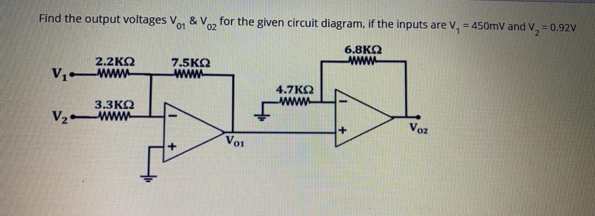
Transcribed Image Text:Find the output voltages Vo1
& V
02
for the given circuit diagram, if the inputs are V, = 450mV and
v,
= 0.92V
6.8K
www
2.2KQ
V1 Www
7.5KQ
www
4.7KO
www.
3.3KQ
V2 www
Voz
Vo1
Expert Solution
This question has been solved!
Explore an expertly crafted, step-by-step solution for a thorough understanding of key concepts.

Step by step
Solved in 2 steps with 2 images

Knowledge Booster


Learn more about
Need a deep-dive on the concept behind this application? Look no further. Learn more about this topic, electrical-engineering and related others by exploring similar questions and additional content below.Recommended textbooks for you
Delmar's Standard Textbook Of Electricity
Electrical Engineering
ISBN:
9781337900348
Author:
Stephen L. Herman
Publisher:
Cengage Learning
Delmar's Standard Textbook Of Electricity
Electrical Engineering
ISBN:
9781337900348
Author:
Stephen L. Herman
Publisher:
Cengage Learning