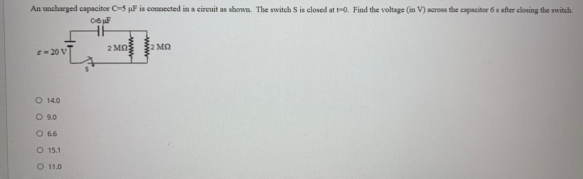
An uncharged capacitor C=5 µF is connected in a circuit as shown. The switch S is closed at t=0. Find the voltage (in V) across the capacitor 6 s after closing the switch. C-5 µF 2 MQ 2 MN E = 20 V O 14.0 O 9.0 O 6.6 O 15.1 O 11.0


Q: A voltage source is connected to the two terminals of a 54.23 µF capacitor. The source voltage…
A:
Q: E = 245 V | R1 = 74 kΩ | R2 = 15 kΩ | R3 = 47 kΩ The capacitor in this circuit initially has no…
A: The given circuit with node markings can be drawn as:
Q: Find the equivalent capacitance seen at the terminals of the circuit C3 40 µF Ceq C1 10μF C2 |10 µF…
A: Given circuit,
Q: A capacitor C = 50 pF is operating at 220 V at a frequency of 50HZ. The real power dissipated in…
A: Resistor dissipates power and is given by the formula, P=I2R. Where R is the resistance of the…
Q: Problem 2 The voltage across a 2-F capacitor is shown in the given figure. Sketch versus time the…
A:
Q: E6.5 The waveform for the current in a 1-nF capacitor is Fig. E6.5. If the capacitor has an initial…
A:
Q: Pt A. Derive the expression for the capacitor voltage for the time interval 0≤t≤10 μs. Pt B. Derive…
A: we need to derive the expression for the capacitor voltage for the time interval 0≤t≤10 μs As per…
Q: n 21 Consider the circuit shown with &= 50 V, R=250 0, L=281 mH, and C=0.5 µF. The open switch is…
A:
Q: A 137 pF capacitor is connected to a voltage source such that ve(t) = 12e-2tV , t>0 and v.(t) = 12…
A:
Q: 20- Equivalent capacitance between a and b points for the capacitor group connected as shown in the…
A:
Q: All capacitors were initially discharged. at t = 0, S1 is placed at position 1 and S2 is closed.…
A:
Q: 3- The voltage across a 10µF capacitor has the waveform shown in the figure. a) Draw the current…
A:
Q: Q.34: The switch in the circuit shown in figure beside has been closed for a long time, and then…
A: Here I am attaching images so that you can understand in very easy manner
Q: In the circuit shown below, the switch has been closed for a long time and is opened at t=0. The…
A:
Q: 8. Consider the series RC circuit below. C= 4.0mF %3D You? F1002 502 a. How should the open switch…
A: Since you have asked multiple questions in a single request, we will be answering only the first…
Q: Find the voltage across the capacitor at t=150 ms if the current through a 5mF capacitor is shown by…
A: Given data, Area of the upper right rectangle, Area of the lower left rectangle,
Q: 5 Ohm SOhm 100hm 10H 10mF
A:
Q: The capacitor in the circuit seen has been charged to 300 V. At t=0, switch 1 closes, causing…
A: Draw the circuit at t = 0.
Q: 6.24.1 In the circuit below, all the capacitors have already reached steady state (no current…
A:
Q: Consider the circuit .1. Find the total energy delivered to the inductor.2. Find the total energy…
A: Since we only answer up to 3 subparts, we will answer first 3. Please resubmit the question and…
Q: A 137 pF capacitor is connected to a voltage source such that ve(t) = 12e-2tV,t>0 and v.(t) = 12 V,…
A: In this question, we need to determine the energy of the capacitor. Energy E= 0.5CV2 Joule.
Q: In the following circuit, the switch was in position 'A' for a long time. At t=0, the switch moved…
A: PRESENCE OF SOURCE In the presence of sources, all the tolerant essentials which are R, L and C…
Q: 1. 7.11 There is no energy stored in the capacitor at the time the switch inthe circuit makes…
A: When switch is at position a
Q: The voltage across a 21-uF capacitor is given by the following function of time, vo Find the Power…
A:
Q: E6.5 The waveform for the current in a 1-nF capacitor is Fig. E6.5. If the capacitor has an initial…
A: In this question we need to find a energy stored in capacitor at t = 6 msec
Q: The voltage at the terminals of the 0.6 µF capacitor shown in the figure is 0 for t < 0 and…
A: The capacitor is a passive element which stores energy in the form of electric field. The current…
Q: The current in a 100-µF capacitor is shown in the figure below. Determine the waveform for the…
A:
Q: The initial voltage across the capacitor shown in (Figure 1) is vc(0+) = 0. Sketch vc(t). Plot the…
A:
Q: Capacitances of 10 μF and 20 μF are connected in parallel, and this pair is then connected in series…
A:
Q: 9. 7.92. b) Suppose the inductor you chose in part (a) has an initial currentof 10 mA. Write an…
A: Given: io= 10 mA
Q: Consider the circuit below. The capacitor was initially discharged. at t = 0, the switch is placed…
A: In this question we need to find a Thevenin voltage seen by the capacitor when switch is at position…
Q: (a) What is the value of C1 required to set fL to 2000 Hz in the circuit (b) Choose the nearest…
A: (a) Write the expression for the input resistance. Rin=RS∥1gm=1.3 kΩ∥15 mS=1.3 kΩ∥0.2 kΩ=1.3 kΩ0.2…
Q: If the switch in the circuit shown to the right has been closed a long time and opens at t = 0,…
A:
Q: An RLC series circuit contains an unknown capacitor, an inductor with an inductance of 40 mH, and a…
A: Given data, Inductance L = 40 mH Resistance R=16 Ω Voltage V = 240 V Frequency f = 60 Hz Current i =…
Q: 3 F 6 F C H 3 F 4 F The equivalent capacitance is |F.
A: The given circuit is shown below: In the above circuit, the 3F and 6F capacitances are connected…
Q: Q.35: For the circuit shown in figure beside. the switch has been in position "a" for a long time.…
A: Under the steady-state condition, it is known that the capacitor is open-circuit. When the switch is…
Q: The voltage at the terminals of the 0.6 μF capacitor shown in the figure is 0 for t < 0 and…
A:
Q: a) How long will it take the capacitor to discharge to 25 v after the switch is closed C 100 V R 2.2…
A: In this question, We need to determine the time to take to reach 25V across the capacitor? And in…
Q: A capacitor has been connected in series with a resistor to a DC source at t=0. If the capacitor has…
A: Vc(t)=V(∞)+((V(0)-V(∞))e-tτ V(0)=2 Convert current source to voltage source V=IsR
Q: 6. A coil having a resistance of 10 Q and an inductance of 0.2 H is connected in series with a…
A: The solution is given below
Q: If the current through a 5 mF capacitor is shown by the waveform below, find the voltage across the…
A:
Q: An RC circuit with components C = 5mF. R = 2k2 and R =3k2 is set as shown in the figure. The…
A:
Q: b) The current in the 50 mH inductor in the figure is known to be 100 mA for t<0. The inductor…
A:
Q: 3. The capacitors in the circuit shown below are charged and the switch closes at t = 0 s. 6Ω #100…
A: In the given circuit a) Total (equivalent) capacitance
Q: 2µF a O 2µF 2µF 3µF 3µF 6µF 3µF 6µF b o
A: The solution is given below
Q: Question 7/12 In the following circuit, if C = 14F; then the energy stored in the capacitor is 1. OA…
A:
Q: t=0 Q.35: For the circuit shown in figure beside, the switch has been in position "a" for a long…
A: For this circuit Initial switch at a position for long time Capacitor act as open circuit after long…
Q: 6.8.2 A capacitor with 1.5 mF capacitance has the terminal voltage t0 thatV = If the vo = 50 and the…
A:
Q: If the current through a 8 mF capacitor is shown by the waveform below, find the voltage across the…
A: Given data, Area in the lower left rectangular portion of the waveform, Area in the upper right…

Step by step
Solved in 4 steps with 4 images

- You are an electrician working in an industrial plant. You discover that the problem with a certain machine is a defective capacitor. The capacitor is connected to a 240-volt AC circuit. The information on the capacitor reveals that it has a capacitance value of 10 mF and a voltage rating of 240 VAC. The only 10-mF AC capacitor in the storeroom is marked with a voltage rating of 350 WVDC. Can this capacitor be used to replace the defective capacitor? Explain your answer.An AC circuit contains a 24 resistor, a 15.9-mH inductor, and a 13.3F capacitor connected in parallel. The circuit is connected to a 240-V, 400-Hz power supply. Find the following values. XL=XC=IR=AIL=AIC=AP=WVARsL=VARsC=IT=AVA=PF=%=At t = 0, the switch S is closed and the capacitors are uncharged. Find the charge stored on capacitor C2 in steady state (t -> infinity). R1 = 2R, R2 = 2R, R3 = 3R, R4 = 2R, R5 = 3R, C1 = 6, C2 = 6.
- To measure the capacitance C of a capacitor, you attach the capacitor to a battery and wait until it is fully charged. You then disconnect the capacitor from the battery and let it discharge through a resistor of resistance RR. You measure the time T1/2 that it takes the voltage across the resistor to decrease to half its initial value at the instant that the connection to the capacitor is first completed. You repeat this for several different resistors. You plot the data as T1/2 versus R and find that they lie close to a straight line that has slope 9.00 μF. What is the capacitance C of the capacitor?The input to the circuit shown in the figure below is the voltage V(t) = 4e-20 t V for t > 0 The output is the current i(t) = -1.2e-20t V for t > 0 The initial inductor current is iL(0) = -3.5 A. Find the values of inductance L and resistance R. Please answer in typing format solution pleaseSuppose that at t=0, we connect an uncharged 10{μF capacitor to a charging circuitconsisting of a 2500-V voltage source in series with a 2{MΩ resistance. At t=40s, the capacitoris disconnected from the charging circuit and connected in parallel with a 5{MΩ resistor.Determine the voltage across the capacitor at t=40 s and at t=100 s. (Hint: You may find itconvenient to redefine the time variable to be t′=t−40 for the discharge interval so that thedischarge starts at t′=0.)
- 9. 7.92. b) Suppose the inductor you chose in part (a) has an initial currentof 10 mA. Write an expression for the current through the inductorfor t≥0.A 10 mH inductor, a 1 μF capacitor, and a variable resistor areconnected in parallel in the circuit shown. The resistor is adjusted so thatthe roots of the characteristic equation are −8000±j6000 rad/s. Theinitial voltage on the capacitor is 10 V, and the initial current in theinductor is 80 mA. Find1. R;2. dv(0+)/dt;3. B1 and B2 in the solution for v; and4. iL(t).A 100V electromotive force is applied to an RC-series circuit in which the resistance is 200 ohms and the capacitance is 10-4 F. Find the charge q(t) on the capacitor if q(0) =0. Find the current i(t).
- GENERAL RLC CIRCUITS: Solve and show your solution completely. Make sure your answers are in 4 decimals places. What capacitance must be placed in series with an inductance of 0.05 henry so that at 100 Hz,the impedance becomes equal to the ohmic resistance?For the figure, the circuit has reached steady state with the switch closed. Now the switch opens. a) Determine the time constant of the de-energized circuit.b) Determine the equation for the inductor current.c) Find the inductor current at time t = 17.8 µS.An RLC series circuit contains an unknown capacitor, an inductor with an inductance of 40 mH, and a resistor with a value of 16 Ω. The circuit is connected to a 240-V, 60-Hz line. If a current of 8 A flows in the circuit, determine the value ofthe unknown capacitor? Show your work. a) 2.575 uF b) 25.75 uF c) 257.5 uF d) 2575 uF