Please can you help me And solve this problem I hope it includes a solution the k-map and logic circuit diagram
Please can you help me And solve this problem I hope it includes a solution the k-map and logic circuit diagram

Delmar's Standard Textbook Of Electricity
7th Edition
ISBN:9781337900348
Author:Stephen L. Herman
Publisher:Stephen L. Herman
Chapter12: Batteries And Other Sources Of Electricity
Section: Chapter Questions
Problem 3PA: An office building uses a bank of 63 lead-acid cells connected in series with a capacity of 80...

Related questions
Question
Please can you help me
And solve this problem
I hope it includes a solution the k-map and logic circuit diagram
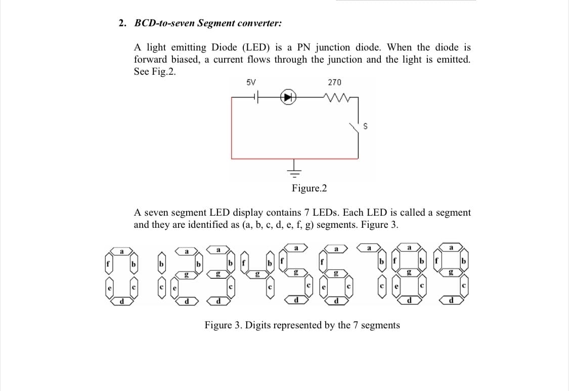
Transcribed Image Text:2. BCD-to-seven Segment converter:
A light emitting Diode (LED) is a PN junction diode. When the diode is
forward biased, a current flows through the junction and the light is emitted.
See Fig.2.
5V
270
Figure.2
A seven segment LED display contains 7 LEDS. Each LED is called a segment
and they are identified as (a, b, c, d, e, f, g) segments. Figure 3.
023456189
a
a
a
d
d
Figure 3. Digits represented by the 7 segments
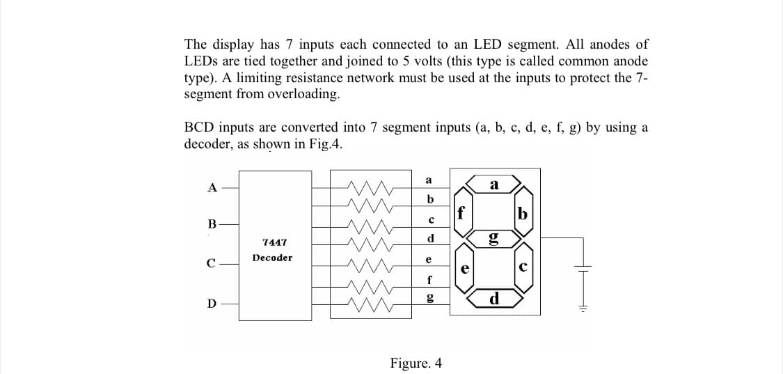
Transcribed Image Text:The display has 7 inputs each connected to an LED segment. All anodes of
LEDS are tied together and joined to 5 volts (this type is called common anode
type). A limiting resistance network must be used at the inputs to protect the 7-
segment from overloading.
BCD inputs are converted into 7 segment inputs (a, b, c, d, e, f, g) by using a
decoder, as shown in Fig.4.
a
A
b
f
В
7447
d
g
Decoder
e
e
с
f
d
D
Figure. 4
Expert Solution
This question has been solved!
Explore an expertly crafted, step-by-step solution for a thorough understanding of key concepts.

Step by step
Solved in 2 steps with 3 images

Knowledge Booster


Learn more about
Need a deep-dive on the concept behind this application? Look no further. Learn more about this topic, electrical-engineering and related others by exploring similar questions and additional content below.Recommended textbooks for you
Delmar's Standard Textbook Of Electricity
Electrical Engineering
ISBN:
9781337900348
Author:
Stephen L. Herman
Publisher:
Cengage Learning
Delmar's Standard Textbook Of Electricity
Electrical Engineering
ISBN:
9781337900348
Author:
Stephen L. Herman
Publisher:
Cengage Learning