Problem 1) The beam AC is simply supported at A and C, having a cross section of 50 mm wide by 150 mm high is subjected to the uniformly distributed load of 250 N/m plus the couple of magnitude 1,500 N-m as shown in Figure 1-A. a) Draw the shear and moment diagrams. b) Determine the maximum flexural stress. c) Determine the flexural stress in the fiber located 20 mm from the top of the beam at a section 3 meters from support A. f RA 4m 250 N/m + Rc 4m. Figure 1 - A 2m 903₁. 1,500N-m c = 75 mm N.A. b- 50 mm h-150 mm Cross-sectional dimensions
Problem 1) The beam AC is simply supported at A and C, having a cross section of 50 mm wide by 150 mm high is subjected to the uniformly distributed load of 250 N/m plus the couple of magnitude 1,500 N-m as shown in Figure 1-A. a) Draw the shear and moment diagrams. b) Determine the maximum flexural stress. c) Determine the flexural stress in the fiber located 20 mm from the top of the beam at a section 3 meters from support A. f RA 4m 250 N/m + Rc 4m. Figure 1 - A 2m 903₁. 1,500N-m c = 75 mm N.A. b- 50 mm h-150 mm Cross-sectional dimensions

Chapter2: Loads On Structures
Section: Chapter Questions
Problem 1P

Related questions

Concept explainers
Question
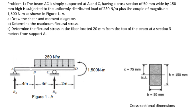
Problem 1) The beam AC is simply supported at A and C, having a cross section of 50 mm wide by 150
mm high is subjected to the uniformly distributed load of 250 N/m plus the couple of magnitude
1,500 N-m as shown in Figure 1- A.
a) Draw the shear and moment diagrams.
Transcribed Image Text:Problem 1) The beam AC is simply supported at A and C, having a cross section of 50 mm wide by 150
mm high is subjected to the uniformly distributed load of 250 N/m plus the couple of magnitude
1,500 N-m as shown in Figure 1-A.
a) Draw the shear and moment diagrams.
b) Determine the maximum flexural stress.
c) Determine the flexural stress in the fiber located 20 mm from the top of the beam at a section 3
meters from support A.
f
RA
4m
250 N/m
+
Rc
4m.
Figure 1 - A
2m
903₁.
1,500N-m
c = 75 mm
N.A.
b- 50 mm
h-150 mm
Cross-sectional dimensions
Expert Solution
This question has been solved!
Explore an expertly crafted, step-by-step solution for a thorough understanding of key concepts.

Step by step
Solved in 6 steps with 5 images

Knowledge Booster


Learn more about
Need a deep-dive on the concept behind this application? Look no further. Learn more about this topic, civil-engineering and related others by exploring similar questions and additional content below.Recommended textbooks for you

Structural Analysis (10th Edition)
Civil Engineering
ISBN:
9780134610672
Author:
Russell C. Hibbeler
Publisher:
PEARSON

Principles of Foundation Engineering (MindTap Cou…
Civil Engineering
ISBN:
9781337705028
Author:
Braja M. Das, Nagaratnam Sivakugan
Publisher:
Cengage Learning
Structural Analysis (10th Edition)
Civil Engineering
ISBN:
9780134610672
Author:
Russell C. Hibbeler
Publisher:
PEARSON
Principles of Foundation Engineering (MindTap Cou…
Civil Engineering
ISBN:
9781337705028
Author:
Braja M. Das, Nagaratnam Sivakugan
Publisher:
Cengage Learning

Fundamentals of Structural Analysis
Civil Engineering
ISBN:
9780073398006
Author:
Kenneth M. Leet Emeritus, Chia-Ming Uang, Joel Lanning
Publisher:
McGraw-Hill Education


Traffic and Highway Engineering
Civil Engineering
ISBN:
9781305156241
Author:
Garber, Nicholas J.
Publisher:
Cengage Learning