Problem 2:- Consider the simple power system below. The reactance data is tabulated in the provided table. T₁ 3 13 G₁ + st 2 CH Subtransient Reactance data in PU Component X² хо X¹ 0.10 0.10 G1 0.05 G2 0.10 0.10 0.05 T1 0.25 0.25 0.25 T2 0.25 0.25 0.25 Line 1-2 0.30 0.30 0.50 1) Draw the positive sequence network impedance model. 2) Draw the negative sequence network impedance model. 3) Draw the zero sequence network impedance model. T₂ & XD t G₂
Problem 2:- Consider the simple power system below. The reactance data is tabulated in the provided table. T₁ 3 13 G₁ + st 2 CH Subtransient Reactance data in PU Component X² хо X¹ 0.10 0.10 G1 0.05 G2 0.10 0.10 0.05 T1 0.25 0.25 0.25 T2 0.25 0.25 0.25 Line 1-2 0.30 0.30 0.50 1) Draw the positive sequence network impedance model. 2) Draw the negative sequence network impedance model. 3) Draw the zero sequence network impedance model. T₂ & XD t G₂

Power System Analysis and Design (MindTap Course List)
6th Edition
ISBN:9781305632134
Author:J. Duncan Glover, Thomas Overbye, Mulukutla S. Sarma
Publisher:J. Duncan Glover, Thomas Overbye, Mulukutla S. Sarma
Chapter2: Fundamentals
Section: Chapter Questions
Problem 2.10P: For the circuit element of Problem 2.3, calculate (a) the instantaneous power absorbed, (b) the real...

Related questions

Question
100%
Power System Analysis
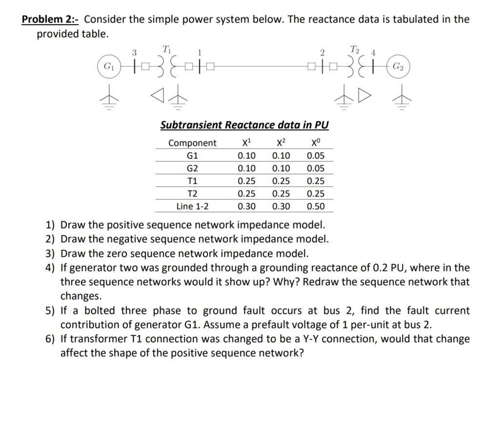
Transcribed Image Text:Problem 2:- Consider the simple power system below. The reactance data is tabulated in the
provided table.
T₁
G₁
ⒸİD
1038010
4+
2
13
T₂ 4
Subtransient Reactance data in PU
Component
X¹
X²
хо
G1
0.10
0.10 0.05
G2
0.10
0.10
0.05
T1
0.25 0.25
0.25
T2
0.25 0.25
0.25
0.30 0.30 0.50
Line 1-2
G₂
Draw the positive sequence network impedance model.
2) Draw the negative sequence network impedance model.
3) Draw the zero sequence network impedance model.
4) If generator two was grounded through a grounding reactance of 0.2 PU, where in the
three sequence networks would it show up? Why? Redraw the sequence network that
changes.
5) If a bolted three phase to ground fault occurs at bus 2, find the fault current
contribution of generator G1. Assume a prefault voltage of 1 per-unit at bus 2.
6) If transformer T1 connection was changed to be a Y-Y connection, would that change
affect the shape of the positive sequence network?
Expert Solution
This question has been solved!
Explore an expertly crafted, step-by-step solution for a thorough understanding of key concepts.

Step by step
Solved in 3 steps with 4 images

Knowledge Booster


Learn more about
Need a deep-dive on the concept behind this application? Look no further. Learn more about this topic, electrical-engineering and related others by exploring similar questions and additional content below.Recommended textbooks for you
Power System Analysis and Design (MindTap Course …
Electrical Engineering
ISBN:
9781305632134
Author:
J. Duncan Glover, Thomas Overbye, Mulukutla S. Sarma
Publisher:
Cengage Learning
Power System Analysis and Design (MindTap Course …
Electrical Engineering
ISBN:
9781305632134
Author:
J. Duncan Glover, Thomas Overbye, Mulukutla S. Sarma
Publisher:
Cengage Learning