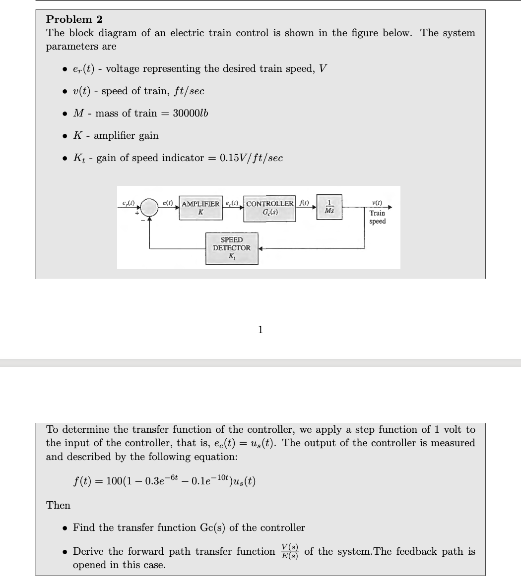
Problem 2 The block diagram of an electric train control is shown in the figure below. The system parameters are • er(t) - voltage representing the desired train speed, V • v(t) - speed of train, ft/sec M - mass of train=30000/b ● K - amplifier gain • Kt - gain of speed indicator = 0.15V/ft/sec e,(1) e(1) AMPLIFIER (1) CONTROLLER ) K G(s) SPEED DETECTOR K₂ 1 -13 Ms v(1) Train speed To determine the transfer function of the controller, we apply a step function of 1 volt to the input of the controller, that is, ec(t) = us(t). The output of the controller is measured and described by the following equation: f(t) = 100(1-0.3e-6t - 0.1e-10t)us(t) Then • Find the transfer function Gc(s) of the controller • Derive the forward path transfer function of the system. The feedback path is opened in this case.
Problem 2 The block diagram of an electric train control is shown in the figure below. The system parameters are • er(t) - voltage representing the desired train speed, V • v(t) - speed of train, ft/sec M - mass of train=30000/b ● K - amplifier gain • Kt - gain of speed indicator = 0.15V/ft/sec e,(1) e(1) AMPLIFIER (1) CONTROLLER ) K G(s) SPEED DETECTOR K₂ 1 -13 Ms v(1) Train speed To determine the transfer function of the controller, we apply a step function of 1 volt to the input of the controller, that is, ec(t) = us(t). The output of the controller is measured and described by the following equation: f(t) = 100(1-0.3e-6t - 0.1e-10t)us(t) Then • Find the transfer function Gc(s) of the controller • Derive the forward path transfer function of the system. The feedback path is opened in this case.

Delmar's Standard Textbook Of Electricity
7th Edition
ISBN:9781337900348
Author:Stephen L. Herman
Publisher:Stephen L. Herman
Chapter29: Dc Generators
Section: Chapter Questions
Problem 16RQ: Explain the difference between cumulative- and differential-compounded connections.

Related questions
Question
2. Hi please below problem given in picture
Transcribed Image Text:Problem 2
The block diagram of an electric train control is shown in the figure below. The system
parameters are
• er(t) - voltage representing the desired train speed, V
• v(t) - speed of train, ft/sec
M-mass of train = 30000lb
•K-amplifier gain
• Kt - gain of speed indicator
f(t)
e, (c)
=
=
0.15V/ft/sec
e(1) AMPLIFIER (1) CONTROLLER (0)
K
Ge(s)
SPEED
DETECTOR
K₂
1
1
Ms
To determine the transfer function of the controller, we apply a step function of 1 volt to
the input of the controller, that is, ec(t) = us(t). The output of the controller is measured
and described by the following equation:
100(1-0.3e-6t_ -0.1e-1⁰t)us(t)
v(1)
Train
speed
Then
• Find the transfer function Gc(s) of the controller
V(s)
• Derive the forward path transfer function of the system. The feedback path is
opened in this case.
Expert Solution
This question has been solved!
Explore an expertly crafted, step-by-step solution for a thorough understanding of key concepts.

Step by step
Solved in 4 steps

Knowledge Booster


Learn more about
Need a deep-dive on the concept behind this application? Look no further. Learn more about this topic, electrical-engineering and related others by exploring similar questions and additional content below.Recommended textbooks for you
Delmar's Standard Textbook Of Electricity
Electrical Engineering
ISBN:
9781337900348
Author:
Stephen L. Herman
Publisher:
Cengage Learning
Delmar's Standard Textbook Of Electricity
Electrical Engineering
ISBN:
9781337900348
Author:
Stephen L. Herman
Publisher:
Cengage Learning