Problem 4: In the Figure shown, the Q8 element has equally-spaced nodes. The nodes 1, 4, 6 of the Q8 element are collapsed into one node; and nodes 7 and 2 are moved towards the collapsed node at a distance equal to one fourth the length of the element sides 1-8 and 1-3 to form an F6 element, as shown below. The F6 element is used to model fracture mechanics problem with the crack tip placed at the collapsed node. 1) Derive x and y in terms of and n for the Q8 element where and n are coordinates of the master element. 2) Modify and derive x and y in terms of and n for the F6 element. η 3) Determine the variation of Exx and Eyy along r. Check for singularity at the collapsed node.
Problem 4: In the Figure shown, the Q8 element has equally-spaced nodes. The nodes 1, 4, 6 of the Q8 element are collapsed into one node; and nodes 7 and 2 are moved towards the collapsed node at a distance equal to one fourth the length of the element sides 1-8 and 1-3 to form an F6 element, as shown below. The F6 element is used to model fracture mechanics problem with the crack tip placed at the collapsed node. 1) Derive x and y in terms of and n for the Q8 element where and n are coordinates of the master element. 2) Modify and derive x and y in terms of and n for the F6 element. η 3) Determine the variation of Exx and Eyy along r. Check for singularity at the collapsed node.

Mechanics of Materials (MindTap Course List)
9th Edition
ISBN:9781337093347
Author:Barry J. Goodno, James M. Gere
Publisher:Barry J. Goodno, James M. Gere
Chapter8: Applications Of Plane Stress (pressure Vessels, Beams, And Combined Loadings)
Section: Chapter Questions
Problem 8.2.8P: A spherical steel pressure vessel (diameter 500 mm, thickness 10 mm) is coated with brittle lacquer...

Related questions

Question
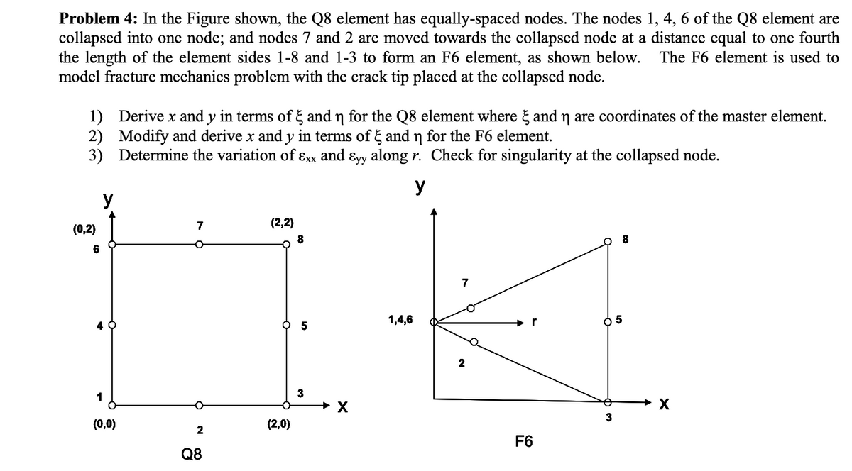
Transcribed Image Text:Problem 4: In the Figure shown, the Q8 element has equally-spaced nodes. The nodes 1, 4, 6 of the Q8 element are
collapsed into one node; and nodes 7 and 2 are moved towards the collapsed node at a distance equal to one fourth
the length of the element sides 1-8 and 1-3 to form an F6 element, as shown below.
model fracture mechanics problem with the crack tip placed at the collapsed node.
The F6 element is used to
1) Derive x and y in terms of g and n for the Q8 element where & and n are coordinates of the master element.
2) Modify and derive x and y in terms of g and n for the F6 element.
3) Determine the variation of ɛxx and ɛyy along r. Check for singularity at the collapsed node.
y
y
7
(2,2)
(0,2)
8
6
7
O 5
1,4,6
r
2
1
3
3
(0,0)
(2,0)
F6
Q8
Expert Solution
This question has been solved!
Explore an expertly crafted, step-by-step solution for a thorough understanding of key concepts.

Step by step
Solved in 4 steps with 5 images

Knowledge Booster


Learn more about
Need a deep-dive on the concept behind this application? Look no further. Learn more about this topic, mechanical-engineering and related others by exploring similar questions and additional content below.Recommended textbooks for you
Mechanics of Materials (MindTap Course List)
Mechanical Engineering
ISBN:
9781337093347
Author:
Barry J. Goodno, James M. Gere
Publisher:
Cengage Learning
Mechanics of Materials (MindTap Course List)
Mechanical Engineering
ISBN:
9781337093347
Author:
Barry J. Goodno, James M. Gere
Publisher:
Cengage Learning