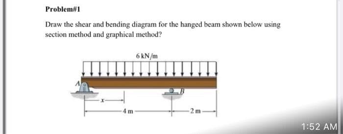
Problem#1 Draw the shear and bending diagram for the hanged beam shown below using section method and graphical method? 6 kN/m 4 m -2m-
Q: The bar(AB) is uniform and weighs (loo N). Delermine the reactions ot (A)and CB)when the bar is in e...
A:
Q: Determine the following based on the diagram below Magnitude of the maximum shear force . Location o...
A: It is required to determine maximum shear force and bending moment
Q: Consider the base excitation system of a mass of 14 kg, 14* + 2x = 2y where y = 2.5 sin(0.32t). To r...
A:
Q: Explain the role of manufacturing in design?
A:
Q: A circular plate of 9m radius is submerged vertically in a tank of water so that its top is 4m to th...
A: Given data: The radius of the circular plate is r=9 m, The mass density of the water is ρ=1000 kg/m...
Q: B: Find the total moment of force with respect to point (A), for the two forces in next fig. 8m 3m 5...
A: Answer: The total moment of force with respect to point (A) is 0 N•m.
Q: Q3 Use the graphing method to find the resultant and its direction of the forces shown in figure 1. ...
A: Given
Q: 2. Knowing that a = 40°, determine the resultant of the three forces shown.
A: According to the details provided in the question, we need to calculate the Resultant and its posit...
Q: Consider laminar flow of water over a flat plate of length 1 m. If the boundary layer thickness at a...
A:
Q: 2. The A water tube boiler operates at 1800 psia has the following characteristics: No. of riser 110...
A: Given DataP=1800 psiaNo. of riser=110Length=110ftTower diameter d=6ft [taken]
Q: A polymer cylinder (2) is clamped between rigid heads by two steel bolts (1). The steel [E = 29,000 ...
A: For steel,αs=6.5×10⁻⁶ /°F,Es=29000 ksi,For polymer,αp=37.2×10⁻⁶ /°F,Ep=350 ksi,Outside diameter of c...
Q: 18 Modulus f elaeticity equal 2 times Bulk modeulus Find Poinson ratio
A: Consider the elastic modulus of the material as E. Consider the bulk modulus of the material as K. C...
Q: 17- Stirling engine can be called as: a) internal combustion engine b) external combustion engine c)...
A: 17. stirling engine can be called as option (b) external combustion engine ...
Q: 7.9 A solid steel shaft of 200 mm diameter transmits 5 MW at 500 rev/min. It is proposed to alter th...
A:
Q: 14 K. Calculate the work done by the gas.
A: To find Work done by the gas
Q: 10. A rough casting for a rotor weighs 450 lb. and is mounted on centres 46 in. apart, ready for mac...
A:
Q: In the following scenario illustrated in the figure, the tool is machining the inside walls of a poc...
A:
Q: Water is flowing in pipeline 600 mm in diameter, 1000-meter long. The pressure at entrance reads 30 ...
A: Given Data D=600 mm L=1000 m P1=30 kPa P2=16 kPa f=0.013
Q: In the example on the pages 29 30, the system will be stable if 0<T <0.2. What are the mathematical ...
A: Given Control system To find Mathematical tools for calculation in the range of 0<T<0.2
Q: Air is heated at constant pressure from 2 7 degrees C to 57 degrees C at 3 bar in a heater from an i...
A: Given Data, p=3 bar, T1=27°CT2=57°C, To=280 K
Q: The tension in AB is about Weight 200 N 108.70 N O 110.40 N 120.60 N 95.50 N
A: GIVEN DATA- A CABLE SYSTEM GIVEN ATTACHED TO THE 200N LOAD WE HAVE TO FIND TENSION IN CABLE AB
Q: A water jet exits from the nozzle to the atmosphere as shown in fig.(1), if the pressure at section ...
A: according to the given details
Q: Water flows through a tube of diameter 30 mm at an average velocity of 1.5 m/s. The properties of wa...
A:
Q: e determine the resultant of the force system in next figure. And locate the resultant with respect ...
A: Given force system
Q: Q3 Use the graphing method to find the resultant and its direction of the forces shown in figure 1.
A:
Q: Air is heated at constant pressure from 27 C to 57 C at 3 bar in a heater from an infinite heat sour...
A: given; temperature (T1)=270c =300Ktemperature(T2)=570c ...
Q: 23- In a four-stroke cycle diesel engine, during suction stroke: a) only air is sucked in b) only pe...
A:
Q: B: Find the total moment of force with respect to point (A), for the two forces in next fig. 8m 3m 5...
A: Given
Q: 10- In a four stroke cycle petrol engine, the inlet valve a) opens at top dead centre and closes at ...
A: This question is based on the concept of ignition engine
Q: projectile is fired with a speed of 1,000 ft/s at a height of 500 ft. Determine the elevation angle ...
A:
Q: Q1/. A fan draws in air freely and discharges through a test duct of cross - section 0.07 m? in whic...
A: Write the formula for the efficiency of the fan. η=PoutPin Here, Pin is the input power, Pout is the...
Q: Q2: A: Draw the Free Body Diagram only of next fig.
A:
Q: What stresses are produced in the bolt and in the tube
A: Given: d1=0.5 in E1=30,000 ksi d2=1 in E2=16000 ksi t=0.125 in L=8 in nut is tightened an addition...
Q: 10. A rough casting for a rotor weighs 450 lb. and is mounted on centres 46 in. apart, ready for mac...
A: The inertia forces associated with the moving masses frequently generate an unbalance of forces in r...
Q: 5. Is it possible to use the Bourdon Scale to measure the pressure of gases in the case of flow? And...
A: Bourdon Scale ****As per our company policy we are supposed to do only one question if you need the...
Q: Find the moment about point O in
A:
Q: The couple moment acting on the beam is 400 N 400 N 200 N 0.2 m 200 N 3m 2 m 300 N 300 N O 640 Nm O ...
A: It is required to determine the moment about support
Q: B: Find the total moment of force with respect to point (A), for the two forces in next fig. Sm 3m 5...
A: Answer: The total moment of force with respect to point (A), for the two forces is 0 N•m.
Q: Use graph above* Two blocks are positioned on surfaces, each inclined at the same angle of 57.6 degr...
A:
Q: Choose and fill the blanks with the correct answer 1. The unit used to measure the force is .. (a.Kg...
A:
Q: The gearing arrangement suitable for this
A: Given; A 2.7 motor is running at 1850 rev/min Power,P=2.7 kW Running at, N=1850 rev/minIt is to be c...
Q: Thermodynamics Answer the following problem with complete solutions. Write legibly A gas go...
A:
Q: Q2 Use the analytical method to find the resultant and its direction of the forces shown in figure 1...
A: Given
Q: forecast sales for feburary 2022 would be
A: Given; For a product; Forecast and actual sales for january 2021 were ; 10 and 20 repectiveley....
Q: The (180 N) force is applied to the end of body OAB. If 0=50 determined the equivalent force couple ...
A: Given DataF=180Nθ=50°
Q: -20 mm diameter bolts fasten two plates being 25 mm thick and 130 mm wide. If the applied tensile lo...
A:
Q: forecast sales for may 2022 would be?
A: Given; For april 2021, for a product; Forecast sales, Fs=25 Actual sales, As=30If the exponental s...
Q: Market demand for springs is 700000 per annum. A company purchases these spring in lots and sells th...
A:
Q: A frain start from rest at Stadion A & accelerate C@ 0.75 m/s for 40s.Ater thet if freue ls, with ro...
A:
Q: A particle moves along the path whose equation is r = 20 ft. If the angle 0 = t² radians, determine ...
A:
Step by step
Solved in 6 steps with 3 images
- The three beams shown have approximately the same cross-sectional area. Beam 1 is a W 14 X 82 with flange plates; beam 2 consists of a web plate with four angles; and beam 3 is constructed of 2 C shapes with flange plates. Which design has the largest moment capacity? Which has the largest shear capacity? Which is the most economical in bending? Which is the most economical in shear? Assume allowable stress values are: = 18 ksi and ra=11 ksi. The most economical beam is that having the largest capacity-to-weight ratio. Neglect fabrication costs in answering parts (c) and (d) above. Note: Obtain the dimensions and properties of all rolled shapes from tables in Appendix F.A frame ABCD is constructed of steel wide-flange members (W8 x 21; E = 30 x ID6 psi) and subjected to triangularly distributed loads of maximum intensity q0acting along the vertical members (see figure). The distance between supports is L = 20 ft and the height of the frame is h = 4 ft. The members are rigidly connected at B and C. Calculate the intensity of load q0 required to produce a maximum bending moment of 80 kip-in. in the horizontal member BC. If the load q0 is reduced to one-half of the value calculated in part (a), what is the maximum bending moment in member BC? What is the ratio of this moment to the moment of 80 kip-in. in part (a)?A rectangular beam with semicircular notches, as shown in part b of the figure, has dimensions h = 0,88 in. and h1 = 0.80 in. The maximum allowable bending stress in the metal beam is emax = 60 ksi, and the bending moment is M = 600 lb-in. Determine the minimum permissible width bminof the beam.
- A wood box beam is constructed of two 260 mm × 50 mm boards and two 260 mm × 25 mm boards (sec figure). The boards are nailed at a longitudinal spacing. b = 100 mm. If each nail has an allowable shear force F = 1200 N. what is the maximum allowable shear force Vmax?Two W 310 × 74 Steel wide-flange beams are bolted together to form a built-up beam as shown in the figure. What is the maximum permissible bolt spacing s if the shear force V = 80 kN and the allowable load in shear on each bolt is F = 13.5 kN. Note: Obtain the dimensions and properties of the W shapes from Table F-l(b).A two-axle carriage that is part of an over head traveling crane in a testing laboratory moves slowly across a simple beam AB (sec figure). The load transmitted to the beam from the front axle is 2200 lb and from the rear axle is 3800 lb. The weight of the beam itself may be disregarded. Determine the minimum required section modulus S for the beam if the allowable bending stress is 17,0 ksi, the length of the beam is 18 ft, and the wheelbase of the carriage is 5 ft. Select the most economical I-beam (S shape) from Table F-2(a), Appendix F.
- For the beam AB shown in Cases 1 and 2, derive and plot expressions for the shear force and bending moment acting on section 1 in terms of the distance x (0 < x< L). [Note: Case 1 results in the conventional V- and M-diagrams, in which the loads are fixed and the location of the section varies; the diagrams for Case 2 (called influence diagrams) show the variation of V and M at a fixed section as the location of the load is varied]The horizontal beam ABC of an oil-well pump has the cross section shown in the figure. If the vertical pumping force acting at end C is 9 kips and if the distance from the line of action ofthat force to point B is 16 ft, what is the maximum bending stress in the beam due to the pumping force?.2 A ligmio.irc ii supported by two vorlical beams consistins: of thin-walled, tapered circular lubes (see ligure part at. for purposes of this analysis, each beam may be represented as a cantilever AB of length L = 8.0 m subjected to a lateral load P = 2.4 kN at the free end. The tubes have a constant thickness ; = 10.0 mm and average diameters dA = 90 mm and dB = 270 mm at ends A and B, re s pec lively. Because the thickness is small compared to the diameters, the moment of inerlia at any cross section may be obtained from the formula / = jrrf3;/8 (see Case 22, Appendix E); therefore, the section modulus mav be obtained from the formula S = trdhlA. (a) At what dislance A from the free end docs the maximum bending stress occur? What is the magnitude trllul of the maximum bending stress? What is the ratio of the maximum stress to the largest stress (b) Repeat part (a) if concentrated load P is applied upward at A and downward uniform load q {-x) = 2PIL is applied over the entire beam as shown in the figure part b What is the ratio of the maximum stress to the stress at the location of maximum moment?
- Two identical, simply supported beams AB and CD are placed so that they cross each other at their midpoints (sec figure). Before the uniform load is applied, the beams just touch each other at the crossing point. Determine the maximum bending moments (mab)max* and (MCD)max beams AB and CD, respectively, due to the uniform load if the intensity of the load is q = 6.4 kN/m and the length of each beam is L = 4 m.A hollow steel box beam has the rectangular cross section shown in the figure. Determine the maximum allowable shear force K that may act on the beam if the allowable shear stress is 36 MPa. cA steel beam is built up from a W 410 × 85 wide flange beam and two 180 mm X 9 mm cover plates (see figure). The allowable load in shear on each bolt is 9.8 kN. What is the required bolt spacing s in the longitudinal direction if the shear force V = 110 kN Noie: Obtain the dimensions and moment of inertia of the W shape from Table F-l(b).