Q 4.12: The DC converter is used to control power flow from a DC voltage, V. = 110 V to a battery voltage. E = 220 V. The power transferred to the battery is 30 kW. The current ripple of the inductor is negligible. Determine (a) the duty cycle 8, (b) the effective load resistance Reg. and (c) the average input current I.
Q 4.12: The DC converter is used to control power flow from a DC voltage, V. = 110 V to a battery voltage. E = 220 V. The power transferred to the battery is 30 kW. The current ripple of the inductor is negligible. Determine (a) the duty cycle 8, (b) the effective load resistance Reg. and (c) the average input current I.

Introductory Circuit Analysis (13th Edition)
13th Edition
ISBN:9780133923605
Author:Robert L. Boylestad
Publisher:Robert L. Boylestad
Chapter1: Introduction
Section: Chapter Questions
Problem 1P: Visit your local library (at school or home) and describe the extent to which it provides literature...

Related questions
Question
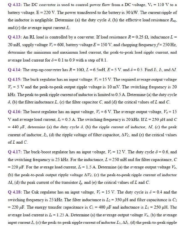
Transcribed Image Text:Q 4.12: The DC converter is used to control power flow from a DC voltage, V; = 110 V to a
battery voltage. E= 220 V. The power transferred to the battery is 30 kW. The current ripple of
the inductor is negligible. Determine (a) the duty cycle d, (b) the effective load resistance Reg.
and (c) the average input current I.
Q 4.13: An RL load is controlled by a converter. If load resistance R= 0.25 2, inductance L =
20 mH, supply voltage V;= 600, battery voltage E = 150 V, and chopping frequencyf= 250 Hz,
determine the minimum and maximunm load current, the peak-to-pcak load ripple current, and
average load current for d = 0.1 to 0.9 with a step of 0.1.
Q 4.14: The step-up converter has R= 102, L=6.5mH. E=5 V. and d= 0.5. Find I. h, and AI.
Q 4.15: The buck regulator has an input voltage. V. = 15 V. The required average output voltage
V: = 5 V and the peak-to-peak output ripple voltage is 10 mV. The switching frequency is 20
kHz. The peak-to-peak ripple current of inductor is limited to 0.5 A. Determine (a) the duty cycle
3, (b) the filter inductance L, (c) the filter capacitor C, and (d) the critical values of L and C.
Q 4.16: The boost regulator has an input voltage, V: = 6 V. The average output voltage, Va = 15
V and average load current, Ia = 0.5 A. The switching frequency is 20 kHz. If L= 250 µH and C
= 440 µF, determine (a) the duty cycle d, (b) the ripple current of inductor, AI, (c) the peak
current of inductor, IE, (d) the ripple voltage of filter capacitor, AVe, and (e) the critical values
of L and C.
Q 4.17: The buck-boost regulator has an input voltage, V: = 12 V. The duty cycle 8 = 0.6, and
the switching frequency is 25 kHz. For the inductance, L=250 mH and for filter capacitance, C
= 220 µF. For the average load current, L = 1.5 A. Determine (a) the average output voltage Va.
(b) the peak-to-peak output ripple voltage AVc. (c) the peak-to-peak ripple current of inductor
AI, (d) the peak current of the transistor I, and (e) the critical values of L and C.
Q 4.18: The Cuk regulator has an input voltage, V: = 15 V. The duty cycle is d = 0.4 and the
switching frequency is 25 kHz. The filter inductance is L2 = 350 uH and filter capacitance is C2
= 220 µF. The energy transfer capacitance is C = 400 µF and inductance is L1 = 250 µH. The
average load current is Io = 1.25 A. Determine (a) the average output voltage Va. (b) the average
input current I. (c) the peak-to-peak ripple current of inductor L1, Alı. (d) the peak-to-peak ripple
Expert Solution
This question has been solved!
Explore an expertly crafted, step-by-step solution for a thorough understanding of key concepts.

This is a popular solution!

Trending now
This is a popular solution!

Step by step
Solved in 2 steps with 2 images

Knowledge Booster


Learn more about
Need a deep-dive on the concept behind this application? Look no further. Learn more about this topic, electrical-engineering and related others by exploring similar questions and additional content below.Recommended textbooks for you
Introductory Circuit Analysis (13th Edition)
Electrical Engineering
ISBN:
9780133923605
Author:
Robert L. Boylestad
Publisher:
PEARSON

Delmar's Standard Textbook Of Electricity
Electrical Engineering
ISBN:
9781337900348
Author:
Stephen L. Herman
Publisher:
Cengage Learning

Programmable Logic Controllers
Electrical Engineering
ISBN:
9780073373843
Author:
Frank D. Petruzella
Publisher:
McGraw-Hill Education
Introductory Circuit Analysis (13th Edition)
Electrical Engineering
ISBN:
9780133923605
Author:
Robert L. Boylestad
Publisher:
PEARSON
Delmar's Standard Textbook Of Electricity
Electrical Engineering
ISBN:
9781337900348
Author:
Stephen L. Herman
Publisher:
Cengage Learning
Programmable Logic Controllers
Electrical Engineering
ISBN:
9780073373843
Author:
Frank D. Petruzella
Publisher:
McGraw-Hill Education

Fundamentals of Electric Circuits
Electrical Engineering
ISBN:
9780078028229
Author:
Charles K Alexander, Matthew Sadiku
Publisher:
McGraw-Hill Education

Electric Circuits. (11th Edition)
Electrical Engineering
ISBN:
9780134746968
Author:
James W. Nilsson, Susan Riedel
Publisher:
PEARSON

Engineering Electromagnetics
Electrical Engineering
ISBN:
9780078028151
Author:
Hayt, William H. (william Hart), Jr, BUCK, John A.
Publisher:
Mcgraw-hill Education,