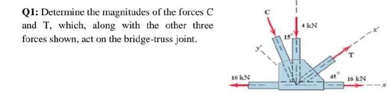
Q1: Determine the magnitudes of the forces C and T, which, along with the other three 4 kN forces shown, act on the bridge-truss joint. 10 kN 45 16 kN
Q: FE Problem 1: Influence Lines of Truss: For the bridge truss shown below, draw the influence line…
A:
Q: F.. :) For the truss shown below, determine the bar force of AB and AD. Also indicate if these…
A:
Q: 3. Determine the force in each member of the truss shown. State whether each member is in tension or…
A:
Q: Q1:- Determine the force in each member of the truss shown. State whether each member is in tension…
A: The free body diagram for the truss is given below,
Q: Note: Answer (FIVE) questions only Q1: Determine the magnitudes of the forces C and T, which, along…
A: Given: The force along +ive x-axis, F1 16 kN The force along –ive x-axis, F2 = 10 kN The force along…
Q: 1 m Determine the horizontal and vertical components of force that the pins A and B exert on the…
A:
Q: The truss shown is subjected to forces P = 68 kN, the length L divided equally, and H = 0.6 m. If…
A: Given DataP=68NH=0.6mP1=151N
Q: The truss has concentrated loads as shown. The wind loads of 25KN are perpendicular to the member…
A:
Q: b. 3 kN IN 4m 18 kN 3m 3m
A:
Q: For the frame and loading shown, determine the force acting on member ABC (a) at B, (b) at C.
A: Given data The force applied is F = 200 N.
Q: Q2/ Determine the forces at the pin ? joint (F) and the roller support (G) 30KN 20 KN 2m B 2m D 2m
A: find the reaction at F and G.
Q: All members of the truss have the same length L=4.2 m. Determine the MAGNITUDE (N) of force…
A:
Q: 9 kN A 3 m B 63.43 Determine the force in each member of the truss shown. State whether each member…
A:
Q: 1. Determine the reactions for the beam loaded as shown 10 kN 20 kN/m 3kN/m 3m* 6m 6m R1 R2
A: The vertical forces acting on the beam is R1+R2=10 kN+3 kN/m×6 m+12×20 kN/m×6 mR1+R2=10 kN+18 kN+60…
Q: Determine the forces in members a) AB, b) AG, c) GF, d) BF, e) BC. Show solution in a letter-size…
A: Given data W1= 13 (kips) W2 = 9(kips) B = 35(deg) A = 7(deg) L1= 3 (ft) L2 = 6 (ft) L3= 7 (ft)
Q: Q2/ Determine the forces at the pin joint (F) and the roller support (G) ? 30KN 20 KN 2m BY 2m D 2m…
A:
Q: The left support of the cable shown is located 10 m below the right support. The lowest point on the…
A: l1=Lh1h1+h2=100×33+13=32.45 ml2=100-32.45=67.55 m H=wl122h1=w32.4522×3=175.5 w vertical reaction at…
Q: Determine the greatest force P that can be applied to the truss so that none of the members are…
A: Given data Maximum tension =4.5kN(T) Minimum tension=3kN(C)
Q: Question 2 If it is known that the center pin A supports one-half of the vertical loading shown. 6…
A:
Q: A machine component is subjected to the forces and couples shown.The component is to be held in…
A: Given Applied loading in the structure To find Rivet hole (a) On line FG (b) On line GH
Q: Q2/ Determine the forces at the pin joint ? (F) and the roller support (G) 30KN 20 KN 2m BY 2m D 2m…
A:
Q: 20 kN 15 kN/m 40 kN.m Q2) Draw the S.F.D and the B.M:D for the beam shown A 2 m- 2 m
A:
Q: 2.4 m D 1.8 m 1.35 m 1.8 m 0.9 m B. a. Which of the following is the most stressed leg(s)? b. If the…
A: Draw the given diagram.
Q: Determine the magnitude of the force (lb) in member CD and BD of the truss shown if P = 326820 lb, Q…
A:
Q: 8. Determine the axial forces in the indicated members of the following trusses by using the method…
A: Consider a section that cuts the member 1, 2, and 3. Draw the free-body diagram of the upper part of…
Q: Question # 2: Determine the force in each of the three cables needed to lift the machine that has a…
A: Solution:
Q: Activity 1. Solve for the force acting on member BD, CD and CE of the Warren Truss shown using…
A: Draw the free body diagram of the truss and find the reactions: Consider the equilibrium of…
Q: Q2/ Determine the forces at the pin joint (F) and the roller support (G) ? 20 KN 30KN 2m By 2m D 2m…
A: find the reactions at the support at F and G.
Q: Question 3 All members of the truss have the same length L=3.2 m. Determine the MAGNITUDE (N) of…
A:
Q: Q2/ Determine the forces at the pin joint (F) and the roller support (G) ? 20 KN 30KN 2m B 2m D 2m E
A:
Q: A machine component is subjected to the forces and couples shown. The component is to be held in…
A: First replace the applied force and couples with an equivalent force -couple system at G.Assume R be…
Q: For the reinforcement shown, Determine by the method of nodes the magnitude of the force on the…
A: Given data F = 321 N P = 123 N a = 2.2 m b = 1.8 m θ= 76°
Q: Part 2 A Pratt roof truss is loaded as shown. Using the method of joints and the method of sections,…
A: “Since you have asked multiple question, we will solve the second question for you. If you want any…
Q: Q2: Draw the S.F. and B.M. diagrams for the beam which is loaded as shown in Fig. Determine the…
A:
Q: Question # 2: Determine the force in each of the three cables needed to lift the machine that has a…
A:
Q: A block is placed on an inclined plane with the following applied load as shown. Determine the…
A: Data given F1 = 200 N F2= 300 N
Q: A F1 = 3.0 lb force is applied to the handles of the vise grip. Determine the magnitude of the…
A: Given: Leta=1.5inb=1inc=3ind=0.75ine=1in
Q: Q2- Use the method of sections to determine the force in member CE. 40 kN s0 kN 40 kN 20 N 40 kN
A:
Q: All members of the truss have the same length L=3.8 m. Determine the MAGNITUDE (N) of force…
A:
Q: 7.12 Two members each consisting of straight and 8.4-in.-radius quarter-circle portions are…
A: Data given - Quarter circle portion radius = 8.2 " Load Wd = 120 lb
Q: termine the minimum value of a horizontal force P applied to the lower block.
A:
Q: The 6-m pole ABC is acted upon by a force P as shown. The pole is held by a ball-and-socket joint at…
A:
Q: Compute the forces Dy, Dx, Gy and AB, by using section method. 20KN 10 KN 10KN D 4m G E 0 6m A i B ↓…
A:
Q: 2. A load of 100 lbs is hung from the middle of a rope, which is stretched between two rigid walls…
A: Given, Weight = 100 lbs
Q: A 1000 kg crate is to be supported by the rope and Pulley arrangement. Determine the required…
A: Mass of the crate, m=1000 kg
Q: Activity 2. Solve for the force acting on members AB, AC and BC of the Warren Truss shown using…
A: Given: The horizontal force is F=300 kN. Draw the free body diagram of joint A. Here, The force…
Q: For the frame and loading shown, determine the internal forces at the point indicated:Point J
A: Draw the free-body diagram of the frame.
Q: For the steel truss and loading shown, determine the magnitude of the force (lb) of member BE,…
A:
Q: The truss shown below is supported by a roller at A and a hinge at B and carries loads at the points…
A: At roller support, there will be only one reaction i.e., Ay(vertically upward) and Ax=0. At hinged…
Step by step
Solved in 2 steps with 1 images
- The beam is supporting a distributed load of w=660 lb/ft. Determine the magnitudes of the resultant internal loadings acting on section b–b through the centroid C on the beam. Show all work and any FBDs that apply.Determine the magnitude of the vertical force C, for the simply supported beam, where w = 11 kips/ft, L1 = 9 ft and L2 = 5 ft.For the truss structure below, if the maximum force that any member can support is 18 kN in tension or 11 kN in compression, determine the maximum force P that can be supported at joint A. Answer must include 1 place after the decimal point and proper units.
- For the steel truss and loading shown, determine the magnitude of the force (lb) of member BE, knowing that x = 12.2 ft, y = 7.8 ft, and P = 28550 lb. Round off only on the final answer expressed in 3 decimal places .Determine the weight of the heaviest cylinder which can be placed in the position shown without exceeding a stress of 50 MN/m2 in the cable BC. Neglect the weight of the bar AB. The cross – sectional area of cable BC is 100mm2.6–10. The maximum allowable tensile force in the members of the truss is (Ft)max=1500 lb, and the maximum allowable compressive force is (Fc)max=800 lb. Determine the maximum magnitude P of the two loads that can be applied to the truss. Take a=8 ft.
- 6.84 Determine the required force P that must be applied at the blade of the pruning shears so that the blade exerts a normal force of 20 lb on the twig at E.Given: F1=5 kN F2=12 kN F3=4 kN F4= 11 kN L=8 m Determine the force in member CF by the method of sections.Determine the magnitude of the force (lb) in member CD of the truss shown if P = 34150 b, Q = 33650 b, and y = 7.2 ft. Round off only on the final answer expressed in 3 decimal places, Instead of units, indicate whether the force is tensile or compressive: use Tif tensile and C if compressive.
- Determine the forces in each member of the right half of the truss using the method of joints. Given: F1=5 kN F2=12 kN F3=4 kN F4= 11 kN L=8 mAll members of the truss have the same length L =4 m. Determine the magnitude (N) of the force supported by member BD if P = 473 N. Round off only on the final answer and expressed in 3 decimal places.A F1 = 3.0 lb force is applied to the handles of the vise grip. Determine the magnitude of the compressive force developed on the smooth bolt shank A at the jaws.