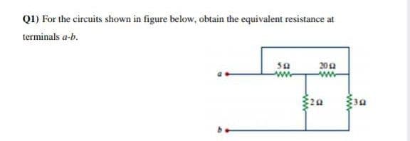
Q1) For the circuits shown in figure below, obtain the equivalent resistance at terminals a-b. 200 ww


Q: For a circuit shown in Figure, find the potential difference between points a and b.
A: The above given circuit can be solved using either of the circuit theory rules mentioned below:…
Q: Non-ideal voltage sources such as batteries are modelled as an independent DC voltage in series with…
A: Find the internal resistance of the battery ?
Q: Discuss the terms resistor, voltage, current and power with examples. plagarisim will be…
A: In the context of electrical energy, voltage, current power definitions are much more important.…
Q: Draw AC equivalent circuit for the circuit given in Figure
A: While drawing ac equivalent figure of a bjt amplifier you must short circut all the capacitors in…
Q: (c) Find the total power consumed in the circuit of Figure Q1(c) by using mesh/loop analysis.
A: The mesh current can be calculated by writing mesh equation to all the meshes and then by solving…
Q: Q2/ Find the voltage average and the voltage waveform for the output of the circuit shown below.…
A:
Q: For the circuit shown below, use the following resistances and reactances. Then, determine the…
A: Given circuit is – Given values are –
Q: Find the currents in the three resistors of the circuit shown in the Figure below. The internal…
A:
Q: At 300 K, an ideal solar cell has a short circuit current of 3A and an open circuit voltage of 0.6V.…
A:
Q: a) Show that the interconnection of the elements satisfies the power check. b) Find the value of the…
A: In this question we need to Show that the interconnection of the elements satisfies the power and…
Q: a.Three conductances G1, G2, and G3 are in series. Write an expression for the equivalentconductance…
A: Given data, The values of conductance as G1, G2, G3. The expression for Geq when it is in series…
Q: A Zener regulated circuit is shown in figure below. If it is needed the V, remains constant and used…
A: In this question, find the ratio of maximum value of resistance RL to minimum value of resistance…
Q: A PMMC instrument gives 27 mA at full scale reading when a potential difference across its terminals…
A: Dear student as per our guidelines we are supposed to solve only one question in which it should…
Q: Q1/ By using thevenins theorem for the circuit shown in Figure below, to find the current in the 3…
A:
Q: ANSWER IN ESSAY FORM What is the purpose of Multisim in terms of circuit creation in relation to…
A: We need to find the purpose of Multisim in terms of circuit creation in relation to Ohms law, and…
Q: The circuit shown in Figure P1.75 contains a voltage-controlled current source. Solve for v s.
A: Given circuit is =
Q: Using the information on the circuit given on the side, find the current strength passing through…
A: Give circuit:
Q: In figure shown, a resistor with three А,В,С. terminals Determine resistance between terminals AD.
A:
Q: 5. A PMMC instrument gives 25mA at full scale reading when a potential difference across its…
A: The solution can be achieved as follows.
Q: Q2/ Find the voltage average and the voltage waveform for the output of the circuit shown below.…
A: The solution can be achieved as follows.
Q: 1. Find v. Note that is the voltage across the 4-ohm resistor. 5 A
A: given
Q: What is the voltage source equivalent when the practical current source is transformed to a…
A:
Q: a) Construct a circuit model for this device using an ideal voltage source and a resistor.
A: (a)
Q: From the circuit shown in the figure,
A:
Q: For a configuration as shown in Figure Q1(b), determine the current through 400 resistor, I4on 300…
A:
Q: *= For the circuit in the given figure, V2(s)/V1(s) C:
A: Given a circuit diagram with resistance and capacitor in series
Q: Find the equivalent resistance Rab in the circuits of Figure below.
A: Since there are multiple questions present, according to company policy we will be answering only…
Q: p1:What's the type logical circuit shown in figure, and find the minimum ransistor to verify work…
A:
Q: A coil having a resistance of 30 ohms and an inductance L is connected in parallel with a resistor…
A: This question belongs to circuit theory . It is based on the concept of power consumption in the…
Q: As referred to a circuit figure q2(b). į)Find current in each branch, determine the total supply|…
A: The solution can be achieved as follows.
Q: A coil of copper wire has a resistance of 10 2 at 20-C. If the temperature coefficient of resistance…
A:
Q: What is the equivalent resistance and the current source equivalent when the practical voltage…
A: In this we will convert practical voltage source into practical current source..
Q: Determine the equivalent resistance Rab in the circuit shown below.
A: Resistance It is the measure of opposition to the current flow in an electrical circuit. The unit of…
Q: Q2/ Find the voltage average and the voltage waveform for the output of the circuit shown below.…
A: In the circuit, Draw tha output voltage waveform and average voltage across Vo This circuit have 2…
Q: Q2/ Find the voltage average and the voltage waveform for the output of the circuit shown below.…
A: The solution can be achieved as follows.
Q: Consider a circuit with two unequal resistances in parallel, then.
A:
Q: For the circuit shown in the following figure. If Vla- 2 V, the miremum value of Ve that will put…
A:
Q: Using the circuit below with R1 = 1 kQ, R2 = 10 kQ, and E = 9 volts, determine the theoretical…
A: To solve the above problem, we will use Ohm's law and Kirchhoff's law. Ohm's law states that current…
Q: calkulate the coupling coefficlent and the energy Stored In thne coupling inductors at t=2sec,for…
A: Given frequency of the circuit is ω=5 rad/sec. Inductance of one coil is calculated as…
Q: If a circuit has two equal parallel resistances connected to a 150V DC power source , then the P.D.…
A:
Q: Obtain the currents and in the Figure below assuming a and b are one node and canddlanother node
A:
Q: Q11. In the circuit in Figure Q11, find v, i, and the power absorbed by the 4-2 resistor. 20V v 310N…
A: While applying Nodal-Analysis at a node,we assume that the current always leaves the concerned node.
Q: RIN = 75 N±%5 ve ROUT = 300 2± %5 b) Design the circuit in the figure with when there is no…
A: Given data: RIN=75±%5 Ω ROUT=300±%5 Ω Solution: To design a given circuit, we have to replace the…
Q: Using Kirchhoff’s rules, a) find the current in each resistor shown in the figure and b) find the…
A:
Q: Q3 Instrument transformers are designed to transform voltage or current from the high values in the…
A: Difference Between current and potential transformer
Q: An example of Simple Resistive Circuits is ,
A: Problem 14: In fluorescent light, the ballast is a resistance. The power supply is connected with…
Q: Q2/ Find the voltage average and the voltage waveform for the output of the circuit shown below.…
A: Draw tha output voltage waveform and average voltage across Vo This circuit have 2 diode.
Q: Use linearity and the assumption that Vo = 1 V to find the actual value of Vo in the figure. Take…
A: The circuit is shown below: Using the linearity the above circuit is simplified as: Vo=i2×2Vo=1…

Step by step
Solved in 2 steps with 2 images


- Using the rules for parallel circuits and Ohmslaw, solve for the missing values. ETE1E2E3E4ITl1I2l3l4RTR182kR275kR356kR462kPT3.436WP1P2P3P4What is the equation of V1 in the figure shown if Vs = 200mV/divThe expression for power is given as the derivative of energy with respect to time. We have studied linear time invariant passive circuits in this course. Which of the following statement expresses the use of power and energy relations in a comprehensive way?Single choice. These can be used for passive and linear circuits These can be used for passive and active linear circuits These can be used for passive linear and non linear circuits These can be used for active and passive nonlinear and linear circuits
- Solve in simple terms and show step by step solution.Using Kirchoff's voltage law to determine the unknown voltage V3 for the configuration given in the figure below. Given that: - The source E= 90 V, - V1= 10 VV and V2= 10.3 VV.A 10-V independent voltage source is in series with a 2-A independent current source. What single source is equivalent to this series combination? Give the type and value of the equivalent source.
- Subject:Circuits INote:Support the problems with circuit diagram and label the pertinent partsPlease with full solutionIn the circuit of the figure, find the value of ZL that will absorb the maximum power and the value of this.THE VOLTAGE AT THE SOURCE IS THE EFFECTIVEFor the network shown in figure (3), if the switch is closed for 2usec and then opened for Susec, find mathematical expressions for vi and in of both periods of time and then plot the waveforms of vL and i as a function of time.
- What approximation do we usually make in circuit theory? -A current-carrying particle is the current. -A current-carrying particle has no charge. -A current-carrying particle does't accelerate. -A current-carrying particle is mythical. -A current-carrying particle is massless Please see diagram for more details.Under DC conditions, in steady state, find the current i and the voltage Vo. Note:Please describe what method/application you are using in each step. (so I can understand it)Given the circuit, solve for: a. using superposition to get the thevenin voltage by R6, what is the contribution of the I1? b. if the load of 250 ohms becomes 100 ohms, what will be the value of Va?