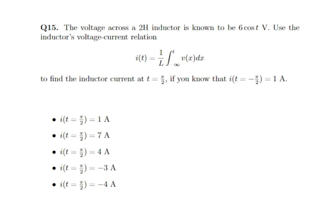
Q15. The voltage across a 2H inductor is known to be 6 cost V. Use the inductor's voltage-current relation 1 i(t) = ²/² v(x) dx 8 to find the inductor current at t =, if you know that i(t = -1) = 1 A. i(t =) = 1 A


Q: The figure below displays a series parallel network R1 R2 Calculate the total resistance of the…
A: here we have to find the total resistance and current.
Q: 3) Find I, in the circuit of Fig. 3.
A: For the given circuit the value of the unknown current need to be calculated. The current can be…
Q: Q3. 5 points Use the mesh-current method to find the pha- sor current I in the circuit shown.…
A:
Q: Find the Thévenin equivalent with respect to the terminals a, b in the circuit in (Figure 1).…
A:
Q: Consider the circuit in (Figure 1). Suppose that R = 0.8 kn. Figure 90 V 2 ΚΩ R www + %6 2.50b 4kQ…
A: here wee have to find the current i
Q: Problems in Design of PCBs for Digital Circuits ● Reflections (causing signal delays and double…
A: We need to discuss problems in Design of PCBs for Digital Circuits i . e. Reflections, Cross-talk…
Q: The inverse z-transform of F(z) is: Select one: O a. f(k)= O b. f(k)= O c. f(k)= O d. f(k)= x (5)* x…
A:
Q: Find V₁, V₂, V3, and V4 R₁ = 1005 R₂=20052 R3=3005 R4 = 4005 R3 + 5V
A:
Q: Calculate values of asked physical quantities of the circuit in the figure. What is the capacitance…
A:
Q: Assigning R3 as the load, find the following: R₁ 4 Ω VS1 = 28V R₂ 2Ω C R₂ (Load) 102 7V VS2…
A:
Q: For the requested latch types, do the following: • Derive the characteristic equation for Q+ in SOP.…
A: According to the question, for the given SR NOR latch as shown below For the requested latch types,…
Q: When looking at a JFET drain characteristic curve, the constant-current region a. can only exist…
A: 33. When looking at a JFET drain characteristic curve, the constant current region ______ A. Can…
Q: (1) Assume that x(+) is a Determine the Nyquist rate a) XU) + x(+-1) 6) x²(+) C) X(1). Cos(wot)…
A: Nyquist rate of signal x(t) is ωo (a) y(t)=x(t)+x(t-1) Apply the Fourier transform on both sides…
Q: Q 1 The power supplied to a three-phase induction motor is 40 kW and the stator losses are 2 kW. If…
A: power supplied to a three-phase induction motor (Pin) = 40 kW Stator losses = 2 kW slip (S) = 4%…
Q: What is the value of the emitter current in mA of the circuit in Figure 2? What is the value of the…
A: the question asked about three parts:- 1. The configuration of the circuit:- which is common base…
Q: You are told to find the transfer function of the following circuit. You know that the transfer…
A: In this question We need to determine the value of B. If R = 9 kΩ, L = 8.9 mH, C = 881 μF, ω =…
Q: etermine the open loop Critical frequency (tool)) the op-amp shown in in fig (a). for this op-amp…
A: (a) The input voltage is 20 mV at 1 kHz The feedback resistance is 82 kΩ The Resistance at negative…
Q: check the numbers, E=21 VCE=7.8 and resistance colector 2.1 Kohms
A:
Q: ar C/m² nr² The charge is placed at the origin with electric flux density. D = a, Find the charge.?
A:
Q: 2. Given the information appearing in Figure 2, determine: Vec a. lc b. Vcc C. B d. Rg www RB TR= 20…
A: We need to find out the current and voltage for given circuit.
Q: In the system shown in Figure 1, the transformers are connected star-star with both star points…
A: In this question we need to find the load current in per unit value
Q: 5) Consider the circuit diagram below. Use superposition to find current Ix as drawn. Draw all…
A:
Q: 2. A 100-m long conductor wire of uniform cross section has a voltage drop of 2 V between its ends.…
A:
Q: Analyze the given circuit and determine which among inputs A, B, C, D, E, F, G, and H, will be…
A: We have to calculate the output z for given different select lines (S2,S1,So) 2*1 MUX circuits
Q: 12- Transmitter has an alphabet of four letters [x1, x2, x3, x4] and the receiver has an alphabet of…
A:
Q: Show the downward shift of the output signal with the series capacitor and diode. Clampers or DC…
A: Solution: Given data Voltage values: Capacitor value: 1000 PFDC offset: 0 VAmplitude: 5 VFreq: 1…
Q: Comparing the AC parameters of the CB and CE amplifiers, the main difference is that the CB…
A:
Q: A 40-MVA, 20-kV/400-kV, Ideal single-phase transformer has the following series impedances: Z₁ =jX₁…
A: In this question We need to equivalent impedance if secondary side is refer into the primary side.…
Q: Find the multiplication factor for an analog wattmeter with a full scale range of 200, if current…
A: Voltage range =300VCurrent range =5A
Q: In the circuit below, determine the power dissipated in the 10ohm resistor .
A: For the given circuit the power absorbed by the 10ohm resistor needs to be calculated. The node…
Q: Ix + Vx O IRIVER₁ R2 VB D₁7 Ideal In the circuit above, plot Ix and IR1 as a function of Vx for two…
A: Given: A circuit, To do: We have to plot Ix and IR1 as function of Vx. a) When VB= -1 V, b) When…
Q: In series resonance the voltages of capacitance and inductance can be much higher than the supply…
A: A series resonance case. To Find- Whether in case of series resonance the voltages of capacitance…
Q: A parallel-plate capacitor is consisted of 25 cm² conducting plates filled by 2-layer dielectric…
A: We need to find out the equivalent capacitance for given diagram and energy stored by capacitor .
Q: What is the preferred D-MOSFET biasing method? O a. Drain-to-source voltage is zero O b.VGS= 0. O c.…
A: Need to identify the best preferred D-MOSFET biassing method from the given list of methods.
Q: 4. In the circuit of Fig. 4, find v(t) & i(t) for t> 0. Assume that v(0)=0 V and i(0)=1 A 4u(1) A…
A: In this question we need to find the voltage v(t) and current i(t) for t>0
Q: What is a BJT transistor and how does it work in amplification and switching circuits?
A: BJT stands for Bipolar Junction Transistor, which is a three-layer semiconductor device capable of…
Q: Design the Ladder program for: = 1₁1213 + (√2+13)(√₂+14) + 1₁ +13 + 14
A:
Q: Q.10 400 KV transmission line has Z = o' 400 Q. If the line is compensated with series capacitor and…
A: In this question we need to find the new value of surge impedance and surge impedance loading.
Q: Is it feasible to take a scientific approach to the Hamming codes that are used to repair errors?…
A: Yes, it is feasible to take a scientific approach to the Hamming codes used to repair errors.
Q: Q2 ) A 220-V, 1.5-hp 50-Hz,wo-pole, capacitor-start induction motor has the following main-winding…
A: As per the guidelines of Bartleby we suppose to answer first three subpart only for solution of…
Q: Calculate values of asked physical quantities of the circuit in the figure. C₁ = 3.0 F C₂ = 4.0 F…
A:
Q: R₁ 4Ω VS1 28V R₂ C 202 R₁ (Load) 10 7V = VS2 THEVENIN'S EQUIVALENT CIRCUIT (TEC) RTH VTH R3 (Load)
A:
Q: a) Write the impedance of the load (Z₁) in the frequency domain. b) Redraw the above circuit and…
A: For the given circuit the total impedance of the circuit and the dot converted circuit need to be…
Q: Which of the following methods is convergence faster to the root; 1) Secant method, 2) Muller…
A: The objective is to determine the method that converge faster to the root.
Q: 3. Let A = (3y-z)a, + 2xza, Wb/m in free space. Find B at point P(3, 0, 2) and the total flux…
A:
Q: b) For the system described above, i. ii. Represent the circuit in Laplace domain. Determine Laplace…
A:
Q: The question is, what exactly is digital audio? What does it mean to convert an analogue signal to a…
A: We need to explain about digital audio and analog to digital converter.
Q: What type of waveform is produced from a bridge rectifier circuit with an open diode? Oa. Half-wave…
A: The output of the bridge rectifier needs to be analyzed when one of the diodes is open and how to…
Q: İn the circuit above, plot İx and İr1 as a function of Vx for two cases : Vx=-1.25V and VB=+1.5V.
A: Given: A circuit, To do: We have to plot Ix and IR1 as function of Vx. a) When VB= -1.25 V, b)…
Q: 1. Find the magnitude of the current density in a sample of silver for which σ= 6.17 x 10⁵ S/m if…
A:

Step by step
Solved in 3 steps

- A 200 Ω resistor, 0.900 H inductor, and 6.00 µF capacitor are connected in series across a voltage source that has voltage amplitude 30.0 V and an angular frequency of 250 rad/s. (a) What are v, vR, vL, and vC at t = 20.0 ms? Compare vR + vL + vC to v at this instant. (b) What are VR, VL, and VC? Compare V to VR + VL + VC. Explain why these two quantities are not equal.A series circuit has a capacitor of 1.5625x10^(-8)F a resistor of 2x10^4 ohms, and an inductor of 1H. If the initial charge on the capacitor is zero,. if a 12-volt battery is connected to the circuit and the circuit is closed at t=0, determine the charge on the capacitor at any time tA 1-F capacitor and initially starts with vC(0) = 0V. (a) Determine iC(t) when vC(t) = x(t), where vC(t) has units of V. (b) Determine vC(t) when iC(t) = x(t), where iC(t) has units of A. Hint: don’t forget the initial conditions. Answer: (0, 4, −4, 0)A, 0V, (2t2−4t+2)V, (−2t2+12t−14)V, 4
- A series LR circuit has a variable inductor with theinductance L(t) is defined by intervals.Find the current i(t) if the resistance is 0.2 ohms, the voltageapplied is E(t) = 4 volts; knowing that i(0) = 0.An RL circuit with a 8-ohm resistor and a 0.08-H inductor carries a current of 1 A at t = 0, at which time a voltage source E(t) = 8 cos (90t) V is added. Determine the subsequent inductor current and voltage.The circuit parameters in the circuit are R=4800 Ω, L=64 mH, C=4 nF, and vg=−72 V.1. Express vo(t) numerically for t≥0.2. How many microseconds after the switch opens is the inductorvoltage maximum?3. What is the maximum value of the inductor voltage?4. Repeat (a)–(c) with R reduced to 480 Ω
- The current in a 20 mH inductor is known to be i=40 mA,t≤0; i=A1e−10,000t+A2e−40.000tA,t≥0. The voltage across the inductor (passive sign convention) is 28 V at t=0. 1. Find the expression for the voltage across the inductor for t>0. 2. Find the time, greater than zero, when the power at the terminals of the inductor is zero.An RLC series circuit contains an unknown capacitor, an inductor with an inductance of 40 mH, and a resistor with a value of 16 Ω. The circuit is connected to a 240-V, 60-Hz line. If a current of 8 A flows in the circuit, determine the value ofthe unknown capacitor? Show your work. a) 2.575 uF b) 25.75 uF c) 257.5 uF d) 2575 uFCalculate the current in an RLC circuit with resistances R=11 ohms, L=0.1 H, and C=10^-2 F that is linked to the source V(t)= 10sin 377t. Assume that the capacitor charge and current are both zero at time t=0.
- A coil having a 240V source has a current of 10.5 A when the frequency is set to 60 Hz. When the frequency is changed to 30 Hz, the resulting current is now 14.3 A. Find the inductance, L, of the coil (in mH).1. A source voltage of an AC series RLC circuit is 120 V. The circuit consists of the ff. quantities: R = 20 Ω, XL = 40 Ω, and XC = 40 Ω. The circuit current (in amperes) is Blank 1. 2. A 9 µF capacitor is in parallel with 3 µF capacitor. If the parallel capacitors is in series with an 8 µF capacitor, the value of total capacitance of the series-parallel connected capacitors is Blank 1.The 0.1μF capacitor in the circuit shown is charged to 100 V. Att=0 the capacitor is discharged through a series combination of a 100 mHinductor and a 560Ω resistor.1. Find i(t) for t≥0.2. Find vC(t) for t≥0.