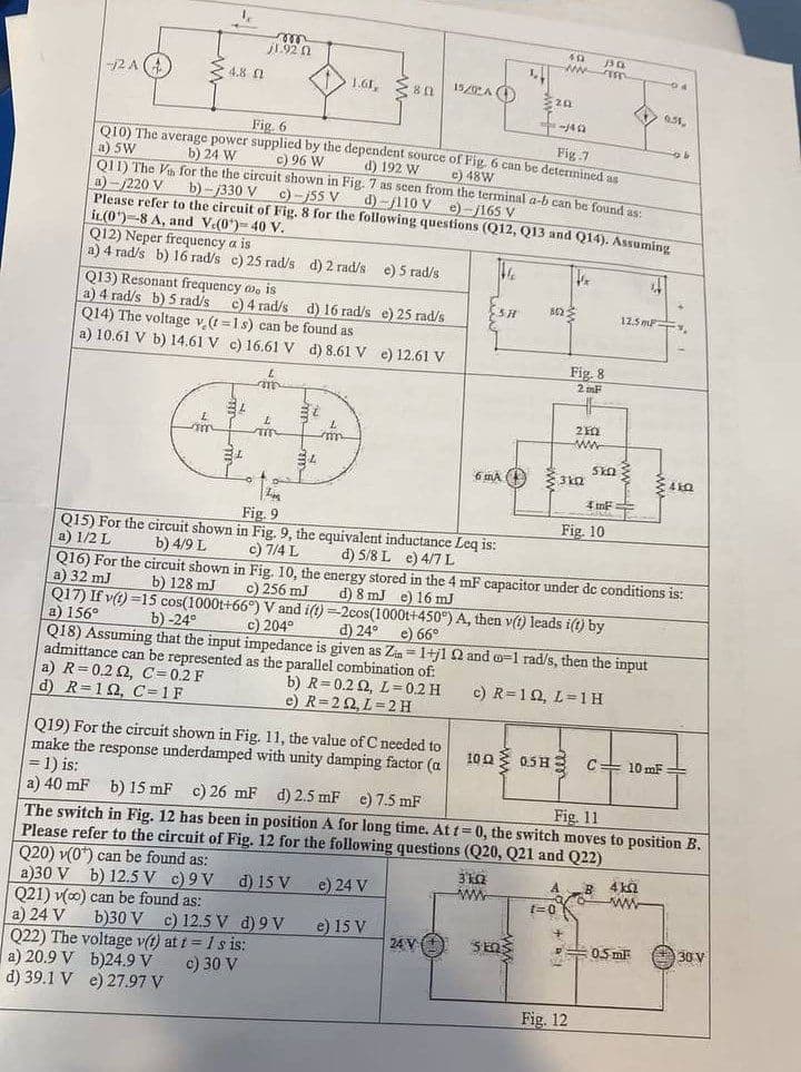
Q19) For the circuit shown in Fig. 11, the value of C needed to make the response underdamped with unity damping factor (a = 1) is: a) 40 mF b) 15 mF c) 26 mF d) 2.5 mF e) 7.5 mF The cuida ni 10 Q www 0.5 H ell C= 10 mF
Q19) For the circuit shown in Fig. 11, the value of C needed to make the response underdamped with unity damping factor (a = 1) is: a) 40 mF b) 15 mF c) 26 mF d) 2.5 mF e) 7.5 mF The cuida ni 10 Q www 0.5 H ell C= 10 mF

Introductory Circuit Analysis (13th Edition)
13th Edition
ISBN:9780133923605
Author:Robert L. Boylestad
Publisher:Robert L. Boylestad
Chapter1: Introduction
Section: Chapter Questions
Problem 1P: Visit your local library (at school or home) and describe the extent to which it provides literature...

Related questions
Question
circuits, pleaseeeee solve questionnn 19
Transcribed Image Text:2A (4)
le
4.8
am
Q12) Neper frequency a is
a) 4 rad/s b) 16 rad/s c) 25 rad/s d) 2 rad/s e) 5 rad/s
Q13) Resonant frequency wo is
a) 4 rad/s b) 5 rad/s
c) 4 rad/s
d) 16 rad/s e) 25 rad/s
Q14) The voltage v (t=1s) can be found as
a) 10.61 V b) 14.61 V c) 16.61 V d) 8.61 V e) 12.61 V
a) R=0.22, C=0.2 F
d) R=192, C=1F
m
1.92 (2
34
149
Fig. 6
Fig.7
Q10) The average power supplied by the dependent source of Fig. 6 can be determined as
a) 5W
b) 24 W
c) 96 W
d) 192 W
c) 48W
Q11) The Va for the the circuit shown in Fig. 7 as seen from the terminal a-b can be found as:
a)-/220 V
d)-110 V )-165 V
b)-/330 V
c)-j55 V
Please refer to the circuit of Fig. 8 for the following questions (Q12, Q13 and Q14). Assuming
it(0)-8 A, and V.(0)-40 V.
te
th
L
m
L
T
1.61, 80
30
34
L
m
1520 A
Z
Fig. 9
Q15) For the circuit shown in Fig. 9, the equivalent inductance Leq is:
a) 1/2 L
d) 5/8 L e) 4/7 L
b) 4/9 L
c) 7/4 L
Q19) For the circuit shown in Fig. 11, the value of C needed to
make the response underdamped with unity damping factor (a
= 1) is:
SH
6 MA
24 V +
L
3k0z
www
492
-NN
202
ΣΕΩΣ
1022
t=0
3kQ
Fig. 8
2mF
HF
210
ww
330
455
+
Fig. 10
SkΩ Σ
4 m²
Q16) For the circuit shown in Fig. 10, the energy stored in the 4 mF capacitor under de conditions is:
a) 32 mJ
d) 8 mJ e) 16 mJ
b) 128 mJ
c) 256 mJ
Q17) If v(t)=15 cos(1000t+66°) V and i(t)-2cos(1000t+450°) A, then v(t) leads i(t) by
a) 156°
b) 0-24°
c) 204°
d) 24°
e) 66°
Q18) Assuming that the input impedance is given as Zin= 1+j1 22 and o-1 rad/s, then the input
admittance can be represented as the parallel combination of:
b) R=0.2 02, L=0.2 H
e) R=202, L=2H
c) R=10, L=1H
100 0.5H C= 10 mF
Fig. 12
a) 40 mF b) 15 mF c) 26 mF d) 2.5 mF e) 7.5 mF
The switch in Fig. 12 has been in position A for long time. At t=0, the switch moves to position B.
Please refer to the circuit of Fig. 12 for the following questions (Q20, Q21 and Q22)
Fig. 11
Q20) v(0) can be found as:
d) 15 V
e) 24 V
a)30 V b) 12.5 V c) 9V
Q21) v(co) can be found as:
a) 24 V b)30 V c) 12.5 V d) 9V
Q22) The voltage v(t) at t = 1 s is:
b)24.9 V c) 30 V
e) 15 V
a) 20.9 V
d) 39.1 V
e) 27.97 V
B
04
f
12.5m.
9.51,
4kQ
www
P0.5 mF
b
410
30 V
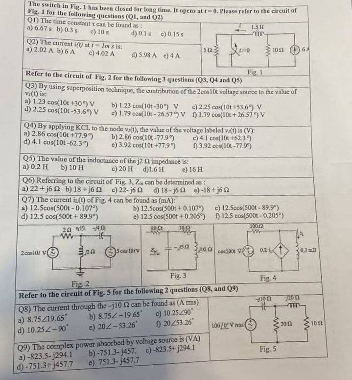
Transcribed Image Text:The switch in Fig. 1 has been closed for long time. It opens at t=0. Please refer to the circuit of
Fig. 1 for the following questions (Q1, and Q2)
Q1) The time constant t can be found as:
a) 6.67 s b) 0.3 s
c) 10 s
Q2) The current i(t) at t- Im s is:
a) 2.02 A b) 6 A
c) 4.02 A
a) 1.23 cos(10t +30°) V
d) 2.25 cos(10t-53.6%) V
d) 0.1 s e) 0.15 s
Fig. 1
Refer to the circuit of Fig. 2 for the following 3 questions (Q3, Q4 and Q5)
Q3) By using superposition technique, the contribution of the 2cos10t voltage source to the value of
vi(t) is:
a) 12.5cos(500t - 0.107°)
d) 12.5 cos(500t + 89.9°)
d) 5.98 A e) 4 A
Q5) The value of the inductance of the j2 02 impedance is:
a) 0.2 H b) 10 H
c) 20 H d)1.6 H
e) 16 H
2cos101 V
Q7) The current in(t) of Fig. 4 can be found as (mA):
2002 -4.0
www
HE
b) 1.23 cos(10t-30%) V
e) 1.79 cos(10t-26.57°) V
Q4) By applying KCL to the node v/(t), the value of the voltage labeled vi(t) is (V):
a) 2.86 cos(10t +77.9°)
b) 2.86 cos(10t-77.9°)
c) 4.1 cos(10t +62.3°)
d) 4.1 cos(10t-62.3°)
e) 3.92 cos(10t +77.9°)
f) 3.92 cos(10t -77.9%)
Q6) Referring to the circuit of Fig. 3, Zen can be determined as:
a) 22+j6 2 b) 18+j62 c) 22-j62 d) 18-j62 e) -18+j6
pa
a)-823.5-j294.1
d)-751.3+j457.7
552
5 cos 10rV
b) 12.5cos(500t+0.107°)
e) 12.5 cos(500t + 0.205°)
10.02
20:2
c) 2.25 cos(10t +53.6%) V
1.79 cos(10t+26.57°) V
1502
1=0
Q9) The complex power absorbed by voltage source is (VA)
b)-751.3-j457. c)-823.5+j294.1
e) 751.3-j457.7
Fig. 2
Fig. 3
Refer to the circuit of Fig. 5 for the following 2 questions (Q8, and Q9)
Q8) The current through the-j10 2 can be found as (Arms)
a) 8.75/19.65*
b) 8.752-19.65*
c) 10.25290*
d) 10.25Z-90°
e) 202-53.26*
f) 20253.26
1.5 H
m
tacos5001 V
c) 12.5cos(500t - 89.9°)
f) 12.5 cos(500t - 0.205°)
100/2
100/0 V ms
1052
0.21
Fig. 4
46
Fig. 5
0.3 mH
720 (2
m
2002
www
10
Expert Solution
This question has been solved!
Explore an expertly crafted, step-by-step solution for a thorough understanding of key concepts.

Step by step
Solved in 6 steps with 5 images

Recommended textbooks for you
Introductory Circuit Analysis (13th Edition)
Electrical Engineering
ISBN:
9780133923605
Author:
Robert L. Boylestad
Publisher:
PEARSON

Delmar's Standard Textbook Of Electricity
Electrical Engineering
ISBN:
9781337900348
Author:
Stephen L. Herman
Publisher:
Cengage Learning

Programmable Logic Controllers
Electrical Engineering
ISBN:
9780073373843
Author:
Frank D. Petruzella
Publisher:
McGraw-Hill Education
Introductory Circuit Analysis (13th Edition)
Electrical Engineering
ISBN:
9780133923605
Author:
Robert L. Boylestad
Publisher:
PEARSON
Delmar's Standard Textbook Of Electricity
Electrical Engineering
ISBN:
9781337900348
Author:
Stephen L. Herman
Publisher:
Cengage Learning
Programmable Logic Controllers
Electrical Engineering
ISBN:
9780073373843
Author:
Frank D. Petruzella
Publisher:
McGraw-Hill Education

Fundamentals of Electric Circuits
Electrical Engineering
ISBN:
9780078028229
Author:
Charles K Alexander, Matthew Sadiku
Publisher:
McGraw-Hill Education

Electric Circuits. (11th Edition)
Electrical Engineering
ISBN:
9780134746968
Author:
James W. Nilsson, Susan Riedel
Publisher:
PEARSON

Engineering Electromagnetics
Electrical Engineering
ISBN:
9780078028151
Author:
Hayt, William H. (william Hart), Jr, BUCK, John A.
Publisher:
Mcgraw-hill Education,