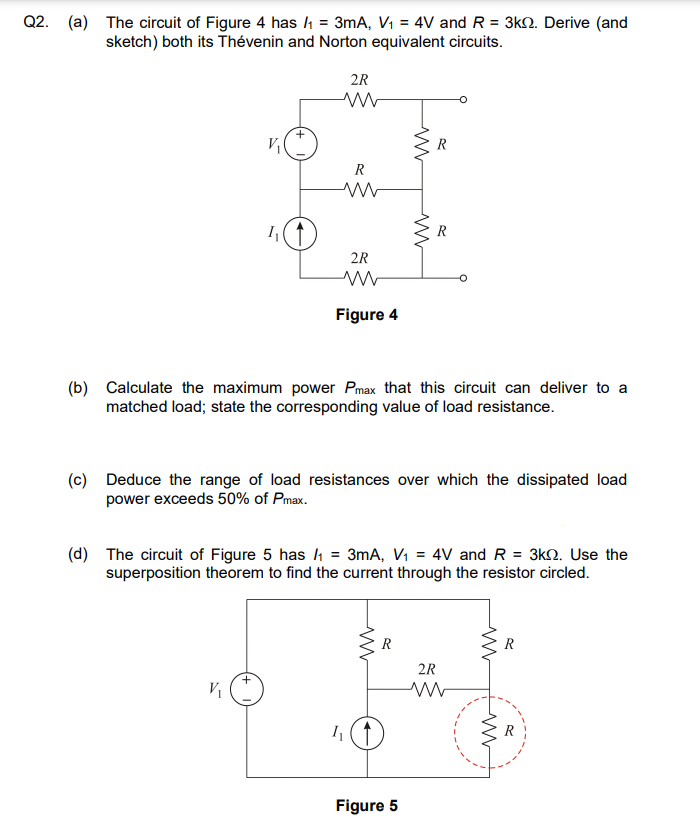
Q2. (a) The circuit of Figure 4 has /₁ = 3mA, V₁ = 4V and R = 3k. Derive (and sketch) both its Thévenin and Norton equivalent circuits. 1₁ 2R V₁ R 2R www Figure 4 (b) Calculate the maximum power Pmax that this circuit can deliver to a matched load; state the corresponding value of load resistance. 4₁ (c) Deduce the range of load resistances over which the dissipated load power exceeds 50% of Pmax. (d) The circuit of Figure 5 has ₁ = 3mA, V₁ = 4V and R = 3k. Use the superposition theorem to find the current through the resistor circled. R ww R R Figure 5 2R ww www ww R R

Introductory Circuit Analysis (13th Edition)
13th Edition
ISBN:9780133923605
Author:Robert L. Boylestad
Publisher:Robert L. Boylestad
Chapter1: Introduction
Section: Chapter Questions
Problem 1P: Visit your local library (at school or home) and describe the extent to which it provides literature...
icon
Related questions
Question

Q2 parts b c & d please

Q2. (a) The circuit of Figure 4 has /₁ = 3mA, V₁ = 4V and R = 3k2. Derive (and
sketch) both its Thévenin and Norton equivalent circuits.
V₁
1₁
+
V₁
2R
www
R
ww
2R
Figure 4
(b) Calculate the maximum power Pmax that this circuit can deliver to a
matched load; state the corresponding value of load resistance.
h
(c) Deduce the range of load resistances over which the dissipated load
power exceeds 50% of Pmax.
ww
(d) The circuit of Figure 5 has /₁ = 3mA, V₁ = 4V and R
= 3kQ. Use the
superposition theorem to find the current through the resistor circled.
www
R
R
Figure 5
R
2R
www
ww
R
Transcribed Image Text:Q2. (a) The circuit of Figure 4 has /₁ = 3mA, V₁ = 4V and R = 3k2. Derive (and sketch) both its Thévenin and Norton equivalent circuits. V₁ 1₁ + V₁ 2R www R ww 2R Figure 4 (b) Calculate the maximum power Pmax that this circuit can deliver to a matched load; state the corresponding value of load resistance. h (c) Deduce the range of load resistances over which the dissipated load power exceeds 50% of Pmax. ww (d) The circuit of Figure 5 has /₁ = 3mA, V₁ = 4V and R = 3kQ. Use the superposition theorem to find the current through the resistor circled. www R R Figure 5 R 2R www ww R
Expert Solution
steps

Step by step

Solved in 4 steps with 4 images

Blurred answer
Knowledge Booster
Pulse Code Modulation
Learn more about
Need a deep-dive on the concept behind this application? Look no further. Learn more about this topic, electrical-engineering and related others by exploring similar questions and additional content below.
Similar questions
  • SEE MORE QUESTIONS
Recommended textbooks for you
Introductory Circuit Analysis (13th Edition)
Electrical Engineering
ISBN:
9780133923605
Author:
Robert L. Boylestad
Publisher:
PEARSON
Delmar's Standard Textbook Of Electricity
Electrical Engineering
ISBN:
9781337900348
Author:
Stephen L. Herman
Publisher:
Cengage Learning
Programmable Logic Controllers
Electrical Engineering
ISBN:
9780073373843
Author:
Frank D. Petruzella
Publisher:
McGraw-Hill Education
Fundamentals of Electric Circuits
Electrical Engineering
ISBN:
9780078028229
Author:
Charles K Alexander, Matthew Sadiku
Publisher:
McGraw-Hill Education
Electric Circuits. (11th Edition)
Electrical Engineering
ISBN:
9780134746968
Author:
James W. Nilsson, Susan Riedel
Publisher:
PEARSON
Engineering Electromagnetics
Electrical Engineering
ISBN:
9780078028151
Author:
Hayt, William H. (william Hart), Jr, BUCK, John A.
Publisher:
Mcgraw-hill Education,