Q1. By first using combinations of resistors, calculate the source current of Circuit 1 and hence calculate the total power dissipated in the resistors. Q2. Use either mesh or nodal analysis to calculate the total power generated by the sources of Circuit 2. Q3. Deduce the Thévenin or Norton equivalent circuit of Circuit 3 and hence calculate the maximum power that this circuit can deliver to a matched load. Q4. A series RL load with R=3002 and L = 0.5mH is connected across the terminals AB of Circuit 3. Sketch a fully-labelled graph of the resulting circuit current through the 302 resistor for t> 0 and calculate the time when the current reaches 80% of its steady-state value. (Note: graph paper is not required). Circuit 1 Circuit 2 Is Circuit 3 Is Vs 2R ww R R w R ww R ww R R ww ww 2R 2R ww 2R 2R ww 18 B Vs
Q1. By first using combinations of resistors, calculate the source current of Circuit 1 and hence calculate the total power dissipated in the resistors. Q2. Use either mesh or nodal analysis to calculate the total power generated by the sources of Circuit 2. Q3. Deduce the Thévenin or Norton equivalent circuit of Circuit 3 and hence calculate the maximum power that this circuit can deliver to a matched load. Q4. A series RL load with R=3002 and L = 0.5mH is connected across the terminals AB of Circuit 3. Sketch a fully-labelled graph of the resulting circuit current through the 302 resistor for t> 0 and calculate the time when the current reaches 80% of its steady-state value. (Note: graph paper is not required). Circuit 1 Circuit 2 Is Circuit 3 Is Vs 2R ww R R w R ww R ww R R ww ww 2R 2R ww 2R 2R ww 18 B Vs

Introductory Circuit Analysis (13th Edition)
13th Edition
ISBN:9780133923605
Author:Robert L. Boylestad
Publisher:Robert L. Boylestad
Chapter1: Introduction
Section: Chapter Questions
Problem 1P: Visit your local library (at school or home) and describe the extent to which it provides literature...

Related questions

Concept explainers
Three-Phase Transformers
Three-segment transformers are a type of transformer used to transform voltages of electrical systems into three ranges. Two type transformers are shell-type transformer and core type transformer. In brief, it could be described because of the exquisite kinds of configurations.
Transformer
Ever since electricity has been created, people have started using it in its entirety. We see many types of Transformers in the neighborhoods. Some are smaller in size and some are very large. They are used according to their requirements. Many of us have seen the electrical transformer but they do not know what work they are engaged in.
Question
Q2 please
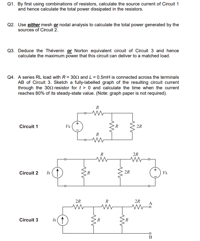
Transcribed Image Text:Q1. By first using combinations of resistors, calculate the source current of Circuit 1
and hence calculate the total power dissipated in the resistors.
Q2. Use either mesh or nodal analysis to calculate the total power generated by the
sources of Circuit 2.
Q3. Deduce the Thévenin or Norton equivalent circuit of Circuit 3 and hence
calculate the maximum power that this circuit can deliver to a matched load.
Q4. A series RL load with R=3002 and L = 0.5mH is connected across the terminals
AB of Circuit 3. Sketch a fully-labelled graph of the resulting circuit current
through the 300 resistor for t> 0 and calculate the time when the current
reaches 80% of its steady-state value. (Note: graph paper is not required).
Circuit 1
Circuit 2 Is
Circuit 3
Is ↑
Vs
+
R
R
ww
www
2R
R
ww ww
ww
R
ww
ww
R
2R
2R
2R
www
2R
MA
93
B
Vs
Expert Solution
This question has been solved!
Explore an expertly crafted, step-by-step solution for a thorough understanding of key concepts.

Step by step
Solved in 2 steps with 2 images

Knowledge Booster


Learn more about
Need a deep-dive on the concept behind this application? Look no further. Learn more about this topic, electrical-engineering and related others by exploring similar questions and additional content below.Recommended textbooks for you
Introductory Circuit Analysis (13th Edition)
Electrical Engineering
ISBN:
9780133923605
Author:
Robert L. Boylestad
Publisher:
PEARSON

Delmar's Standard Textbook Of Electricity
Electrical Engineering
ISBN:
9781337900348
Author:
Stephen L. Herman
Publisher:
Cengage Learning

Programmable Logic Controllers
Electrical Engineering
ISBN:
9780073373843
Author:
Frank D. Petruzella
Publisher:
McGraw-Hill Education
Introductory Circuit Analysis (13th Edition)
Electrical Engineering
ISBN:
9780133923605
Author:
Robert L. Boylestad
Publisher:
PEARSON
Delmar's Standard Textbook Of Electricity
Electrical Engineering
ISBN:
9781337900348
Author:
Stephen L. Herman
Publisher:
Cengage Learning
Programmable Logic Controllers
Electrical Engineering
ISBN:
9780073373843
Author:
Frank D. Petruzella
Publisher:
McGraw-Hill Education

Fundamentals of Electric Circuits
Electrical Engineering
ISBN:
9780078028229
Author:
Charles K Alexander, Matthew Sadiku
Publisher:
McGraw-Hill Education

Electric Circuits. (11th Edition)
Electrical Engineering
ISBN:
9780134746968
Author:
James W. Nilsson, Susan Riedel
Publisher:
PEARSON

Engineering Electromagnetics
Electrical Engineering
ISBN:
9780078028151
Author:
Hayt, William H. (william Hart), Jr, BUCK, John A.
Publisher:
Mcgraw-hill Education,