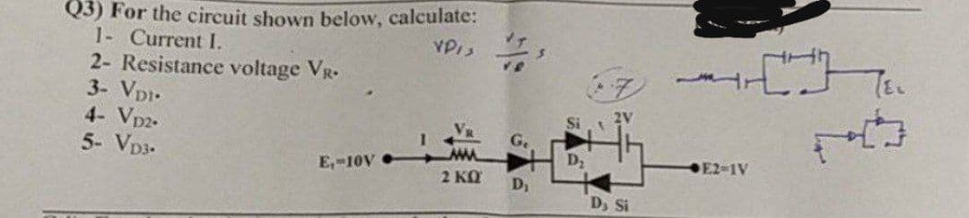
Q3) For the circuit shown below, calculate: VPIS 1- Current I. 2- Resistance voltage VR. 3- VDI- 4- VD2. 5- VD3- E₁-10V 2 ΚΩ D₁ D₂ 2V Dy St [] E2-1V


Q: 7.2 Use the differential equation approach to find v(t) for t> 0 in Fig. E7.2. Plot the esponse. t =…
A: We need to find out voltage across capacitor in the given circuit
Q: ii) Find IDTFT of X(ejw)= е-jw/² for - <<
A: Given: IDTFT of Xejω=e-jω2 -π<ω<π
Q: Find current i, in the ideal transformer circuit shown 292 ww 1:3 12 cos 21 V 692
A: given here a magnetic coupled circuit and asked to find the current ix .
Q: Find the overall susceptance across terminal a-b when Vs = -2 sin(4t + 310°) V. 2Ω 4 H ΖΩ a Vs b M…
A: Susceptance:- It the imaginary part of the admittance. Admittance Y = G ± jB…
Q: Q2: For the circuit of fig.(3), the voltage and current sources are given in a form of Fourier…
A: The circuit diagram is shown below, Where,Vt=50+40 sinωt+30 sin3ωt+25 sin5ωt+30…
Q: Find the total current outward directed from a two meter cube with center at the origin and edges…
A: For the above given current density we need to calculate the value of total current which is…
Q: Describe how a complex wave is produced from sinusoidal waveforms. Give an example to demonstrate…
A: Harmonics are unwanted high frequencies that interfere with the fundamental and create a distorted…
Q: 1. Sketch the output waveform for the following: a.) + 1kQ2 +8 V Si V₂ 4 V -8 V 16
A:
Q: Q1: Answer two of the following questions: a) For the circuit shown in fig.(1), v = 10e * V and i =…
A: As per the guidelines of Bartleby we supposed to answer first three subpart only for solution of…
Q: Bandwidth occupied by 100 MHz carrier; AM modulated by signal frequency of 10 kHz is?
A: Given, Carrier frequency, fc=100 MHz Modulating frequency, fm=10 kHz
Q: Balanced 3 Phase Supply A +PC- A +CC C Line-to-line supply voltage is 380 V with the phase sequence…
A: Methods of three phase power measurement One wattmeter method Two wattmeter method Three wattmeter…
Q: 40. Given that fc(ol) = 100 Hz, Aol = 50 dB, and fc(cl) = 3 kHz, determine the closed-loop gain in…
A: The required parameters can be calculated by using the unity gain bandwidth and the closed loop…
Q: 9. In air, a lossless transmission line of length 50 cm with L=10µH/m, 40PF/m is operated at 25 MHz.…
A:
Q: Q3) Suppose that x(t) is real-valued signal, then show that: b) if x(t) is odd, then X(f) = -2jf…
A: For the above given question we need to calculate the fourier transform of the given signal under…
Q: Q1 Write a sequence of instruction to poll switch at 17 of 74F244 that is connected to port 0. ALE…
A: The given figure is shown below:
Q: For the systems below, determine "Time invariant/variant," "Linear/Non-linear" and…
A: Since you have posted a question with multiple sub-parts, we will solve first three subparts for…
Q: Find IDTFT of X(ejw)= e^(-jw/2) for -π
A: For the above given discrete time fourier transform we need to calculate its inverse discrete time…
Q: (C)- Draw the mechanical characteristic of shunt and series DC motors.
A: DC series motor: The armature & field windings of series DC motor are connected in series with…
Q: B. Find the receiving impedance
A:
Q: Find the overall susceptance across terminal a-b when Vs =
A: In this question we will find overall susceptance across ab...
Q: 8. A transmission line has a characteristic impedance of 500 and a resistanc of 0.1 02/m. If the…
A: In this question we will find attenuation constant for distortionless transmission line....
Q: A- for the function below, the domain and the range is respectively y = |x|-2
A: Given: Domain and range of y=x-2
Q: Q3) In the circuit shown in Figure 3, the load consumes 600 VA with a power factor of 0.8. Determine…
A:
Q: Prove dx(t)/dt________Laplace_ _sX(s)
A: Laplace transform is used to analyze the continous time domain signal into s domain or frequency…
Q: Resistance of 800 2 has a conductance of O125 millisiemens O 1.25 millisiemens 12.5 millisiemens…
A: Given: Resistance, R=800 Ω
Q: A 100 V carrier peak changes from 160 V to 40 V by a modulating signal. The modulation factor is (a)…
A: Given, A 100 V carrier peak changes from 160 V to 40 V by a modulating signal.
Q: Q2 i) a) b) Find DTFT of X[n] = 8[n+5] -a" 8[n-5] X[n]=(n-1) (1/3)^ u[n]
A:
Q: One of the following is not a law for power factor calculation. O P/S O cose O Q/P O P/VI
A:
Q: Present Next state state Flip-flop inputs ABC ABC T TB TC 000 001 0 0 1 001 011 0 1 0 010 XXX X X X…
A: In this question we need to make kmap and electrical circuit of the given counter
Q: 7- when the temperature of PV module increases
A: Given: When the temperature of the PV module increases
Q: Question 3: For the electrical network shown in Figure 3, solve the following: i) Sketch the…
A: To sketch the frequency response of the system. To Determine the output yt given the system is…
Q: The antenna current of an A.M. transmitter is 8 A when only carrier is sent, but it increases to…
A: Given: Antenna current when only carrier is sent , Ic=8 A Antenna current when carrier is modulated,…
Q: Find ix and the power developed in the dependent current source, 2vx.
A: in the given circuit, we have to find ix and power developed in dependent current source 2Vx.
Q: The frequency of the supply to the stator of a 4-pole induction motor is 60 Hz and the rotor…
A: Speed is calculated as given below
Q: 5. The propagation constant of a transmission line with impedance and admittance of 9 and 16…
A:
Q: Find VR (t) for all time t. 4 V 202 F t= t=0 2 H + VR202
A: For the above given question we need to calculate the value of resistor voltage for all time t.…
Q: Exercise 4-1: (a) Determine the resonant frequency for the Wien-bridge oscillator in Fig. 4-9. Use…
A: Wein bridge oscillator circuit using op amp is a basic electronic circuit which is positive feedback…
Q: Q4) a Design a 4 input averaging amplifier.
A:
Q: Q1 A system has a characteristic equation L(s) = K(s+2)/s (s+5) (s^2+2s+5) +K (s+2) Find the range…
A:
Q: Maximum end-end throughput. Consider the scenario shown below, with 10 different servers (four…
A: Throughput is measure the send data through a network. Delay depends the number of host and…
Q: Q3) Draw the output waveform for the circuit in figure below. Assume that +Vout(max) = +10 V and -…
A: By knowing the property of zener diode and operation amplifier we need to plot output waveform of…
Q: 1. Design a 8 - to - 1 multiplexer using 2-to-1 multiplexer using blocks.
A: We are authorized to answer one question at a time, since you have not mentioned which question you…
Q: What is the correct notation for a load factor? a) Ω b) ∞ c) ∑ d) ⅄
A:
Q: Find the total current outward directed from a two meter cube with center at the origin and edges…
A: In the above given question they have mentioned a current density which is in cartesian co-ordinate…
Q: Q5. Calculate the maximum and minimum collector curr (fig. 6) and find Icsat. and VCEsat. RB = 250…
A: Given circuit is shown below. I=IC+IB Apply KVL at input side 15=IRC+IBRB+0.714.3=IC+IBRC+IBRB
Q: >- The open circuit and short circuit tests on a 10 KVA, 125/250 V, 50 Hz single phase transformer…
A:
Q: 10 Given the potential V = sin cos , (a) Find the electric flux density D at (2, π/2, 0). (b)…
A: In this question potential is given...We have to find out electric flux density D and work done to…
Q: Q3) a Find laplace transform of X (t)= et sin 2t for t ≤0 also indicate R.O.C
A: For the given question we need to calculate the Laplace transform of a continuous time domain signal…
Q: G/Verify the following identities Zanh ( x + y) = tanhx + tanky 1 + tanha tanhy
A:
Q: In the below given figure, two capacitances are in series with a 18V source. The capacitance of the…
A: The detailed solution is provided below. The formulae used is given below.

Step by step
Solved in 2 steps with 2 images


- Using the diagram, solve for the Rth, Vth, and load current (IL) through each resistance using Thevenin’s Theorem. Please draw the circuit diagram for each Rth and Vth computation.Using the following values for the circuit in the figure, find what is required in the questions? For the circuit in the figure, find the ones requested in the questions by using the following values? VDD= 30 V, IDSS=8 mA, VP=-6V, R1=110 MΩ, R2=18 MΩ RD=1.9 kΩ, RS=9.12 kΩ VD=? VS=? VDS=?Prove that VDS > VGS − VTH (saturation mode) in the circuit below. Show your complete solution.
- For the circuit in the figure, find the ones requested in the questions by using the following values? VDD= 30 V, IDSS=8 mA, VP=-6V, R1=110 MΩ, R2=18 MΩ RD=1.9 kΩ, RS=3,68 kΩ VG=? VGS=? ID=? VD=? VS=? VDS=?Using the following values for the circuit in the figure, find what is required in the questions? For the circuit in the figure, find the ones requested in the questions by using the following values? VDD= 30 V, IDSS=8 mA, VP=-6V, R1=110 MΩ, R2=18 MΩ RD=1.9 kΩ, RS=9.12 kΩ VG=? VGS=? ID=? VD=? VS=? VDS=?Need help with this Question The D-MOSFET circuit shown in Figure Q1(b) has IDSS = 3 mA and VGS(off) =−8 V. Given the following:R1 = 50 kΩR2 = 150 kΩRD = 1 kΩRS = 2 kΩVDD = +10 VVSS = −10 VDetermine VGS, ID and VDS.
- If R0= 44 milliohms and Ri= 736 ohms, what is R1 , R2, R3 in the equivalent circuit????Consider the circuit shown in the figure. Note that two currents are shown. Calculate the emfs ε1 and ε3.Use Kirchhoff’s laws to determine, for the network shown in Figure below, the current flowing in (a) the 20 Ω resistance, and (b) the 4 Ω resistance. Determine also (c) the p.d. across the 8 Ω resistance, and (d) the active power dissipated in the 10 Ω resistance
- a) Compare metallic foil vs semiconductor strain gauges (construction, advantages and disadvantages). b) Consider a Wheatstone bridge circuit (Figure 1) that has all resistances equal to 250 ?. The resistance R1 is a strain gauge that cannot sustain a power dissipation of more than 0.25 W. What is the maximum applied voltage that can be used for this bridge circuit? At this level of bridge excitation, what is the bridge sensitivity?Use the thevenin equivalent resistance and Vth =?. a) Calculate and plot the current flowing through the pn junctions of device #2 on your 3311 wafer as a function of voltage over the range of -3 volts to plus 1.5 (or so) volts on a linear scale. b) plot the I-V curve for the forward voltage on a log scale. c) What voltages correspond to 10 A/cm2, 100 A/cm2, 1000 A/cm2, 10,000 A/cm2 and 100,000 A/cm2? d) What is the current and current density when the applied voltage is equal to the built-in voltage? e) what are your thoughts on applying a voltage greater than the built-in voltage to a pn junction diode?