Q4 (a) Figure Q4(a) shows the idealized stress-strain curve for steel and Figure Q4(b) shows the yielding of the beam section due to bending. Explain in detail the relation between these TWO (2) Figures based on your understanding of plastic analysis.
Q4 (a) Figure Q4(a) shows the idealized stress-strain curve for steel and Figure Q4(b) shows the yielding of the beam section due to bending. Explain in detail the relation between these TWO (2) Figures based on your understanding of plastic analysis.

Steel Design (Activate Learning with these NEW titles from Engineering!)
6th Edition
ISBN:9781337094740
Author:Segui, William T.
Publisher:Segui, William T.
Chapter1: Introduction
Section: Chapter Questions
Problem 1.5.6P: The data in Table 1.5.3 were obtained from a tensile test of a metal specimen with a rectangular...

Related questions
Question
Question 4a pls
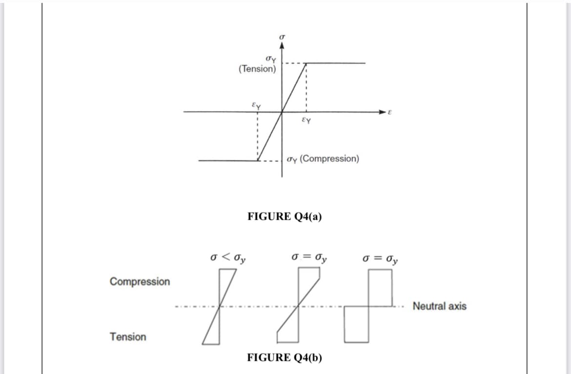
Transcribed Image Text:Oy
(Tension)
Ey
oy (Compression)
FIGURE Q4(a)
o < Oy
o = Oy
0 =
Compression
Neutral axis
Tension
FIGURE Q4(b)
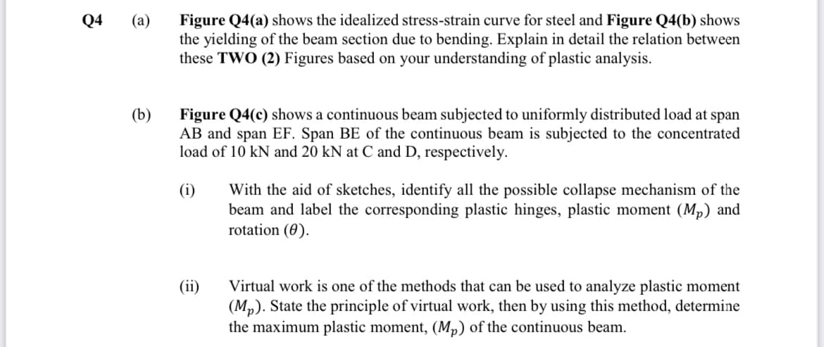
Transcribed Image Text:Q4
Figure Q4(a) shows the idealized stress-strain curve for steel and Figure Q4(b) shows
the yielding of the beam section due to bending. Explain in detail the relation between
these TWO (2) Figures based on your understanding of plastic analysis.
(а)
(b)
Figure Q4(c) shows a continuous beam subjected to uniformly distributed load at span
AB and span EF. Span BE of the continuous beam is subjected to the concentrated
load of 10 kN and 20 kN at C and D, respectively.
(i)
With the aid of sketches, identify all the possible collapse mechanism of the
beam and label the corresponding plastic hinges, plastic moment (Mp) and
rotation (0).
(ii)
Virtual work is one of the methods that can be used to analyze plastic moment
(Mp). State the principle of virtual work, then by using this method, determine
the maximum plastic moment, (Mp) of the continuous beam.
Expert Solution
This question has been solved!
Explore an expertly crafted, step-by-step solution for a thorough understanding of key concepts.

Step by step
Solved in 3 steps with 3 images

Knowledge Booster


Learn more about
Need a deep-dive on the concept behind this application? Look no further. Learn more about this topic, civil-engineering and related others by exploring similar questions and additional content below.Recommended textbooks for you
Steel Design (Activate Learning with these NEW ti…
Civil Engineering
ISBN:
9781337094740
Author:
Segui, William T.
Publisher:
Cengage Learning
Steel Design (Activate Learning with these NEW ti…
Civil Engineering
ISBN:
9781337094740
Author:
Segui, William T.
Publisher:
Cengage Learning