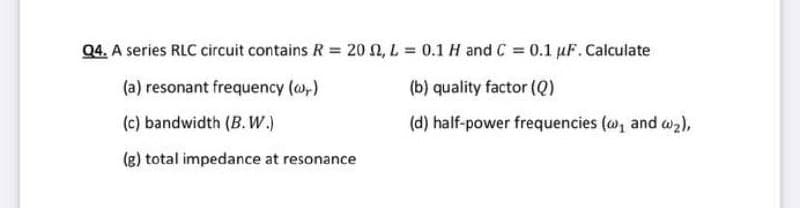
Q4. A series RLC circuit contains R = 20 N, L = 0.1 H and C = 0.1 uF.Calculate %3D (a) resonant frequency (@,) (b) quality factor (Q) (c) bandwidth (B. W.) (d) half-power frequencies (@, and w2), (g) total impedance at resonance


Q: (a) Design an active high-pass filter circuit using op-amp and calculate the value of the capacitor,…
A:
Q: QUESTION 4 Z-transfom of any discrete -time signal can be defined using expression below, +00 X(Z) =…
A:
Q: Ql: For the circuit shown in figure. Derive an expression for Av=V/Vs at high frequency and wH for…
A: The given device is an n-channel JFET
Q: Vcc +9 V Bpc = Bac = 125 Che = 25 pF Che = 10 pF Rc 220 Ω Determine the critical frequencies…
A: Given data, βDC=125βac=125Cbe=25 pFCbc=10 pFRC=220 ΩRE=100 ΩC1=1 μFC2=10 μFC3=1 μFRL=680 ΩR1=12…
Q: Vee La (W),degrecs (70 VIN YO Vous 30 10 Cx 20 Re 10 1-E+13 Frequency råd lsee I.E+12 1.E + 08 LET09…
A: A common emitter amplifier with the circuit shown in the figure : Given the values of the…
Q: 4.3 Home work 1- In the circuit that shown in Figure 4.1. Prove that V1=Q.V at resonance frequency.…
A: Since you have asked multiple questions in a single request, we will be answering only the 1st…
Q: The gain of an amplifier is given by A=1000[ 1+j(f/fB) ]2 Determine the upper half-power frequency…
A: Given gain of the amplifier Calculating magnitude of gain at upper half power frequency (fB…
Q: O As a student, you are required to design a parallel resonance circuit with a resistance of 3 kO.…
A: We need to analyse the given parallel resonance circuit .
Q: R= 300 ohm, L= 40 mH, C= 600nF, V(AC)=5 Volt, F= 100 Hz Calculate theoretically the voltages XL…
A: A series RLC circuit is in resonance condition acts as purely resistive circuit. Because at…
Q: The bode plot is a standard approach to feedback control systems analysis and design. The transfer…
A: Given transfer function is =
Q: Reduce the circuits and calculate the natural frequencies (ω0) and damped resonance frequencies (ωd)…
A: Given: R1=10ΩR2=2ΩR3=20ΩC1=150μFC2=300μFL1=150mHL2=80mH
Q: Q) Draw and find the equivalent cct, low and high frequency responses, and overall gain (Av)? Hint:…
A: Equivalent circuit of the low and high frequency response -:
Q: Using the Bode plot in Fig. 2, find the transfer function, the gain margin, phase margin, zero dB…
A: The 0dB frequency and 180-degree frequency can be easily identified from the given graph and these…
Q: Figure 5 shows a self-bias n-channel JFET amplifier construction while Table 1 listed all the…
A: The required parameters can be calculated by using the DC and AC analysis of the amplifier circuit.…
Q: gm1 = gm2 = 1mS, Cx = 1pF, and Rx = 75kiloohms. Ignore channel length modulation and all other…
A: The circuit is as shown below,
Q: Apply Mason’s Rule to calculate the transfer function of the system represented by following Signal…
A:
Q: 3rd Class Electronic Circuit Homework (1): Frequency Response Q) Draw and find the equivalent cct,…
A: For DC circuits, all capacitors are open circuited. For AC circuits, all independent voltage sources…
Q: If the mid-band gain of an RC coupled amplifier is 150, the low-frequency voltage gain is 70 at an…
A: Given, Mid band gain of RC coupled amplifier, Av,M=150 Low frequency voltage gain Av,L=70 Input…
Q: Explain the cases why tuned filters or detuned filters are used in power distribution system. Give…
A:
Q: Design a series resonant circuit with an input source voltage of 1020° V to have the following…
A: Given: Input source voltage, V=10∠0° Peak current, I=800mA Bandwidth, B.W.=120Hz Resonant frequency,…
Q: The voltage gain of an amplifier is described in the s-domain as shown below. R1 1 R2|| 'sC2} Av(s)…
A: Given
Q: A series circuit comprises an inductor, of resistance 10 Q and inductance 159 pH, and a variable…
A: To solve above problem, one should have basic idea about working of AC circuits. Above given circuit…
Q: Two resistors RI = 100 Ô and R2 200 Q, has temperature of 300 K and 400 K, respectively. If the two…
A:
Q: Q2: The circuit shown is used to pass different frequency bands by changing capacitor's value. If…
A: Hello. Since your question has multiple sub-parts, we will solve the first three sub-parts for you.…
Q: a) from the rootlocus fig , Write the open loop transfer function of the system, b) What is the…
A: Hello, since you have posted a question with multiple subparts and not specified which part to…
Q: CMI + Cgs = (1+gm(r,l|RpL))Cgd + Cgs, so C, is clearly >> %3D Cgd. This means that fol << f» since…
A:
Q: 1- The varactor resonator shown is resonant at 135 MHz. In the circuit, L 150 nH, CT,-12 pF, Cp 5…
A: Given data, f=135 MHzL=150 mHCT=12 pFCP=5 pFCj=20 pF
Q: If bandwidth of an amplifier is 3 MHz and its gain is 4 then find value of unity gain bandwidth…
A: UGB= AOL × fOL HERE AOL =4 is maximum gain fOL =3MHz
Q: Which of the five circuit elements are more effective when it comes to maximizing the gain-bandwidth…
A: The explanation is as follows.
Q: For the circuit in the figure, assuming that the op-amp is ideal in all respects: 1. Derive an…
A:
Q: Q4: Design a four-section bandpass lumped-element filter with a maximally flat response. The…
A: The Given is to Design four-section band-pass lumped-element filter The Given Bandwidth is 5% with a…
Q: an we obtain a plot of XL against frequency f experimentally
A: Inductance- Inductor twists in many turns are called inductor or coil inductance does not depend…
Q: Q3) Find the quality for the circuit shown in Fig.2 by using approximat resonant circuit. SOKO 5 mH…
A: Given:- Parallel RLC circuit Here, Supply current (I)= 2mA Inductance (L)= 5mH Capacitance (C)…
Q: a series RLC circuit, what does it mean that resonance has been reached? Develop a detaile
A: SERIES RLC CIRCUIT:
Q: iii) Find the damping coefficient, resonant frequency and describe the circuits damping…
A: Given the circuit, as shown below: a) We need to find the damping co-efficient, resonant frequency…
Q: Q) Draw and find the equivalent cct, low and high frequency responses, and overall gain (Av)? Hint:…
A: Above showed amplifier is a CE amplifier with potential Divider Bias Configuration So, Its…
Q: , Determine the transfer function, C(S)/R(s) using Mason's gain ferme from the following signal flow…
A: Mason's Gain Formula: T=∑n=1KPn∆n∆Where,Pn=nthPathK=Total path in given…
Q: 4. The Bode plot shown below represents the voltage gain of a particular amplifier. Sketch the input…
A: Consider the input of the amplifier, The input of the amplifier is given. If the magnitude and the…
Q: fT = 500 MHz, rx = 300 Ω, Cμ = 0.75 pF, CGS = CGD = 2.5 pF. Simulate the frequency response of the…
A: Given: fT=500 MHz rx=300Ω Cμ=0.75pF CGS=CGD=2.5 pF The given circuit diagram is,
Q: If the output power from an audio amplifier is measured at 120W when the signal frequency is 1kHz,…
A:
Q: Which of the following is the gain value and oscillation frequency that will allow the system to…
A: In this question, we will find value of k and w for system to be oscillate...
Q: b) The magnitude plot of a transfer function G(s)=- shown in Figure Q4b. Determine K, a and b from…
A:
Q: 752. See Figure 752. D=5. The Bode gain and phase plots for a RC circuit are shown in the fig.…
A:
Q: Q) Draw and find the equivalent cct, low and high frequency responses, and overall gain (Av)? Hint:…
A: Draw the given circuit;(ref question) we need to draw the ac equivalent of the circuit at low and…
Q: 1. In a transistor amplifier how is a small ac signal defined? 2. Why are capacitors and voltage…
A: We need to answer in a transistor amplifier how is a small AC signal defined. Also we need to…
Q: Derive the transfer function º for the signal flow graph shown Figure 8. Y6 Y1 H, H H2 Y H4 5,
A: According to the question we have to find the value of the transfer function Y6/Y1.
Q: Discuss parallel tuned circuit with special reference to resonant frequency, circuit impedance and…
A: “Since you have asked multiple questions, we will solve the first question for you. If you want any…
Q: A receiver is invented by US engineer Edwin Armstrong, which it converts high frequency to low…
A: Superheterodyne Receiver The Superheterodyne Receiver is a radio receiver that uses a technique of…
Q: Q) Draw and find the equivalent cct, low and high frequency responses, and overall gain (Av)? Hint:…
A: For DC circuits, all capacitors are open circuited. For AC circuits, all independent voltage sources…
Q: Calculate the noise voltage at the input of a Television RF amplifier using a device that has a…
A:

Step by step
Solved in 3 steps

- Determine the overall transfer function for the system as shown in Figure Q4.Q4 The figure below shows the Bode plot of a stable plant. We use a proportional controller to increase as much as possible the LFG (Low frequency gain) considering that there is a requirement of a gain margin of 10 dB. From the options, choose the appropriate value for kp. The value of kp is _________AMPLIFIER'S FREQUENCY RESPONSE 4
- If bandwidth of an amplifier is 3 MHz and its gain is 4 then find value of unity gain bandwidth frequency.Referring to the transfer curve below, determine Id at Vgs = 2 V.Impedance measurement in biomedical application modelsPRE LabExercise (Due at the beginning of lab): Analyze how the impedance of the circuit changes when the input signal frequency changes from 0 to infinite.? print the answer on keyboard and Correct or will dislike
- In the circuit diagram shown, if V_BE = 0.7 V, what is the value of the input resistance R_in (base) at mid frequencies?( NEED only handwritten solution please otherwise downvote)Apply Mason’s Rule to calculate the transfer function of the system represented by following Signal Flow GraphDescribe what the terms Gain Bandwidth Product (GBP) and Slew Rate mean inthe context of an operational amplifier. Use the aid of diagrams for yourexplanations.
- calculate both quality factor Q and resonance frequency if it existsR= 300 ohm, L= 40 mH, C= 600nF, V(AC)=5 Volt, F= 100 Hz Calculate theoretically the voltages XL (Inductance = Resistance of the coil), XC (Capacitance = resistance of the capacitor), Z (Impedance = Equivalent resistance of the circuit), VL, VC, VLC and the current value I (mA). Also explain the relationship of XL and XC with frequency in two words. Write the relation that gives the resonant frequency.- Discuss the concept poles and zeros towards stability of the system. - Discuss the concept of bode diagram towards stability of the system. - Discuss the concept of root locus towards stability of the system. I want clear answers without any Plagiarism