Q4. Suppose the circuit shown has the given characteristics at resonance. Determine: a) the value of L. b) the value of R. c) the values of w, and w2. d) the value of V at resonance. - V (volts) V BW=5 krad/s 0.707 v,- R 3.6 mA /0 T0.4 µF (krad/s) 12.5
Q4. Suppose the circuit shown has the given characteristics at resonance. Determine: a) the value of L. b) the value of R. c) the values of w, and w2. d) the value of V at resonance. - V (volts) V BW=5 krad/s 0.707 v,- R 3.6 mA /0 T0.4 µF (krad/s) 12.5

Delmar's Standard Textbook Of Electricity
7th Edition
ISBN:9781337900348
Author:Stephen L. Herman
Publisher:Stephen L. Herman
Chapter15: Alternating Current
Section: Chapter Questions
Problem 4RQ: 4. What is frequency?

Related questions
Question
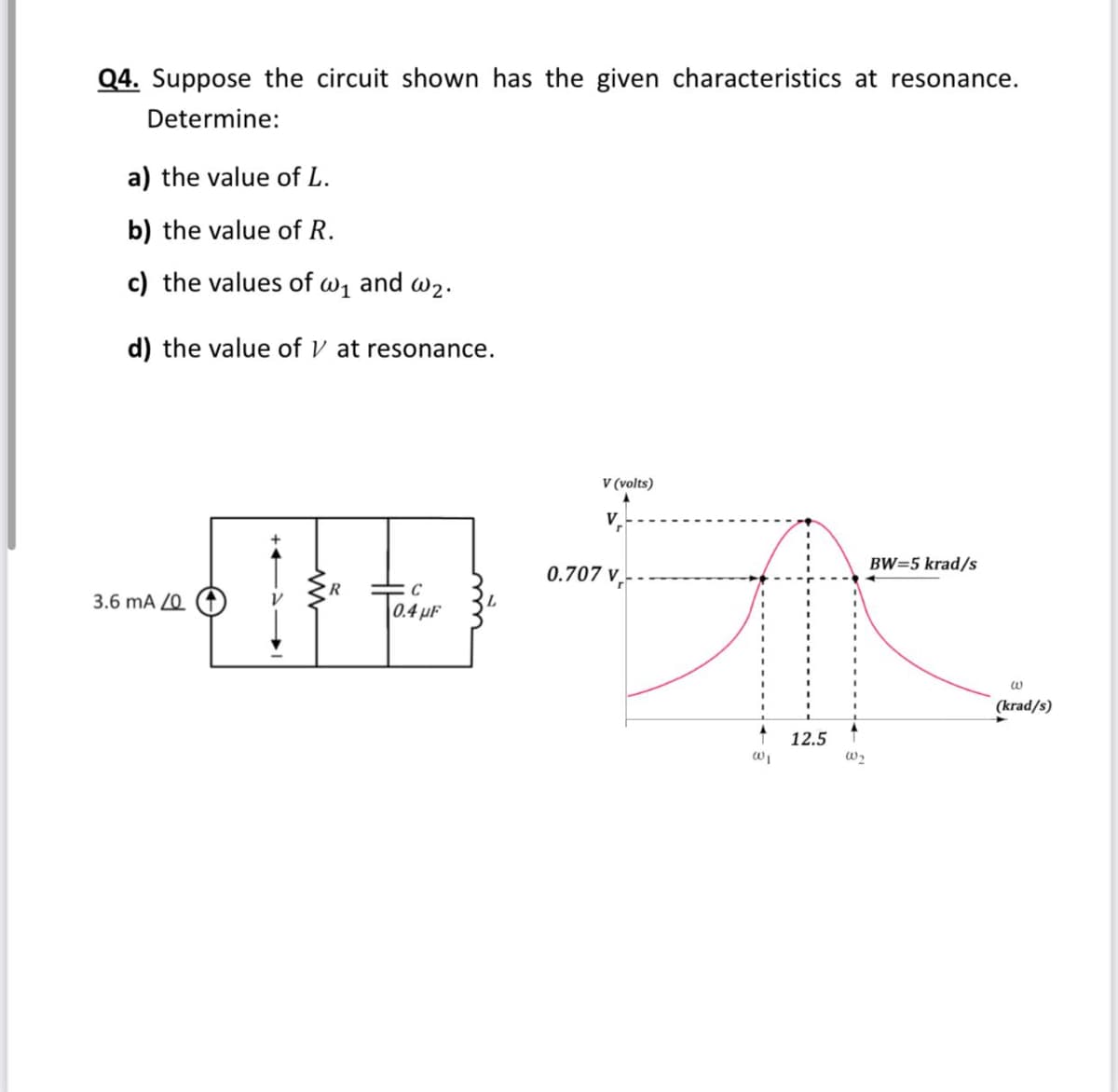
Transcribed Image Text:Q4. Suppose the circuit shown has the given characteristics at resonance.
Determine:
a) the value of L.
b) the value of R.
c) the values of w1 and w2.
d) the value of V at resonance.
V (volts)
V
BW=5 krad/s
0.707 v.-
R
3.6 mA Z0
0.4 µF
(krad/s)
12.5
Expert Solution
This question has been solved!
Explore an expertly crafted, step-by-step solution for a thorough understanding of key concepts.

Step by step
Solved in 2 steps with 1 images

Knowledge Booster


Learn more about
Need a deep-dive on the concept behind this application? Look no further. Learn more about this topic, electrical-engineering and related others by exploring similar questions and additional content below.Recommended textbooks for you
Delmar's Standard Textbook Of Electricity
Electrical Engineering
ISBN:
9781337900348
Author:
Stephen L. Herman
Publisher:
Cengage Learning
Delmar's Standard Textbook Of Electricity
Electrical Engineering
ISBN:
9781337900348
Author:
Stephen L. Herman
Publisher:
Cengage Learning