Q5: For the networks shown in figure (6), determine the maximum power delivered to R3. R1 12Ω 120 VE |12A R 20 2 R,2
Q5: For the networks shown in figure (6), determine the maximum power delivered to R3. R1 12Ω 120 VE |12A R 20 2 R,2

Power System Analysis and Design (MindTap Course List)
6th Edition
ISBN:9781305632134
Author:J. Duncan Glover, Thomas Overbye, Mulukutla S. Sarma
Publisher:J. Duncan Glover, Thomas Overbye, Mulukutla S. Sarma
Chapter2: Fundamentals
Section: Chapter Questions
Problem 2.17MCQ: Consider the load convention that is used for the RLC elements shown in Figure 2.2 of the text. A....

Related questions
Question
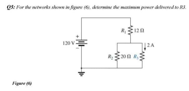
Transcribed Image Text:Q5: For the networks shown in figure (6), determine the maximum power delivered to R3.
R120
120 v=
12A
R2
: 20 Ω R.
Figure (6)
Expert Solution
This question has been solved!
Explore an expertly crafted, step-by-step solution for a thorough understanding of key concepts.

Step by step
Solved in 3 steps with 2 images

Recommended textbooks for you
Power System Analysis and Design (MindTap Course …
Electrical Engineering
ISBN:
9781305632134
Author:
J. Duncan Glover, Thomas Overbye, Mulukutla S. Sarma
Publisher:
Cengage Learning
Power System Analysis and Design (MindTap Course …
Electrical Engineering
ISBN:
9781305632134
Author:
J. Duncan Glover, Thomas Overbye, Mulukutla S. Sarma
Publisher:
Cengage Learning