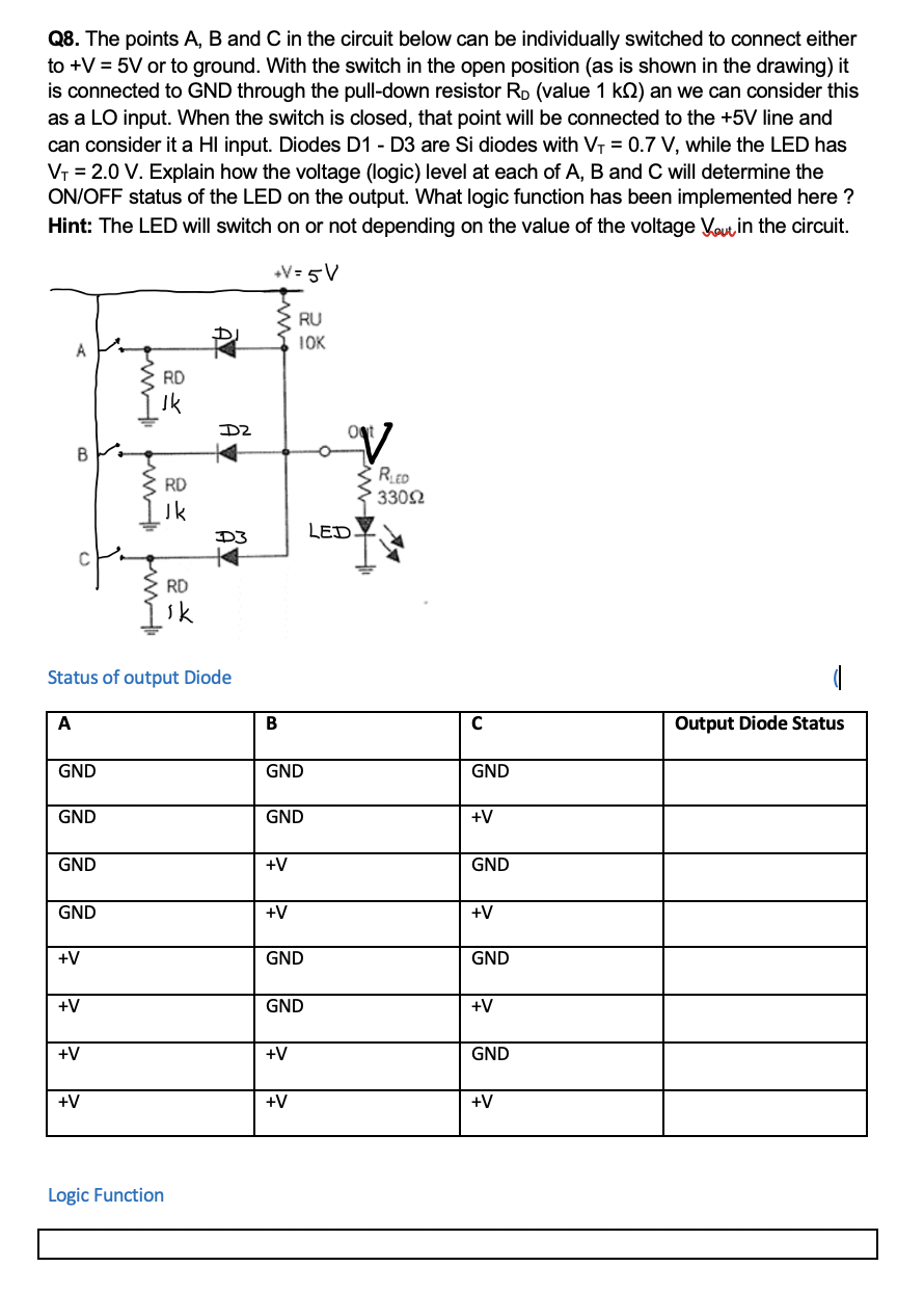
Q8. The points A, B and C in the circuit below can be individually switched to connect either to +V = 5V or to ground. With the switch in the open position (as is shown in the drawing) it is connected to GND through the pull-down resistor Rp (value 1 kQ) an we can consider this as a LO input. When the switch is closed, that point will be connected to the +5V line and can consider it a HI input. Diodes D1 - D3 are Si diodes with VT = 0.7 V, while the LED has VT = 2.0 V. Explain how the voltage (logic) level at each of A, B and C will determine the ON/OFF status of the LED on the output. What logic function has been implemented here ? Hint: The LED will switch on or not depending on the value of the voltage Vouin the circuit. +V= 5V RU IOK RD Ik RED RD 3302 Jk LED. RD sk Status of output Diode A В Output Diode Status GND GND GND GND GND +V GND +V GND GND +V +V +V GND GND +V GND +V +V +V GND +V +V +V w tw tw
Q8. The points A, B and C in the circuit below can be individually switched to connect either to +V = 5V or to ground. With the switch in the open position (as is shown in the drawing) it is connected to GND through the pull-down resistor Rp (value 1 kQ) an we can consider this as a LO input. When the switch is closed, that point will be connected to the +5V line and can consider it a HI input. Diodes D1 - D3 are Si diodes with VT = 0.7 V, while the LED has VT = 2.0 V. Explain how the voltage (logic) level at each of A, B and C will determine the ON/OFF status of the LED on the output. What logic function has been implemented here ? Hint: The LED will switch on or not depending on the value of the voltage Vouin the circuit. +V= 5V RU IOK RD Ik RED RD 3302 Jk LED. RD sk Status of output Diode A В Output Diode Status GND GND GND GND GND +V GND +V GND GND +V +V +V GND GND +V GND +V +V +V GND +V +V +V w tw tw

Related questions
Question
questiion attatched
Transcribed Image Text:Q8. The points A, B and C in the circuit below can be individually switched to connect either
to +V = 5V or to ground. With the switch in the open position (as is shown in the drawing) it
is connected to GND through the pull-down resistor Rp (value 1 k2) an we can consider this
as a LO input. When the switch is closed, that point will be connected to the +5V line and
can consider it a HI input. Diodes D1 - D3 are Si diodes with VT = 0.7 V, while the LED has
Vr = 2.0 V. Explain how the voltage (logic) level at each of A, B and C will determine the
ON/OFF status of the LED on the output. What logic function has been implemented here ?
Hint: The LED will switch on or not depending on the value of the voltage Vout in the circuit.
V= 5V
RU
IOK
A
RD
RED
3302
RD
LED
D3
RD
Status of output Diode
A
B
Output Diode Status
GND
GND
GND
GND
GND
+V
GND
+V
GND
GND
+V
+V
+V
GND
GND
+V
GND
+V
+V
+V
GND
+V
+V
+V
Logic Function
AZ
Expert Solution
This question has been solved!
Explore an expertly crafted, step-by-step solution for a thorough understanding of key concepts.

This is a popular solution!

Trending now
This is a popular solution!

Step by step
Solved in 3 steps with 1 images
