Question 1 (a) Use Kirchhoff's Current Law to write equations at each node (except the reference node) for the circuit shown in Figure Qu. 1. If IA = 2 A, IB = 4 A, R1 = 2 Q, R2 = 3 Q, R3 = 5 Q, R4 = 1 Q, R3= 4 Q, solve for the (b) voltages V1, V2 and V3 using Cramer's rule. R1 Vị R2 V2 R4 V3 R3 R5 IB IA Figure Ou. 1
Question 1 (a) Use Kirchhoff's Current Law to write equations at each node (except the reference node) for the circuit shown in Figure Qu. 1. If IA = 2 A, IB = 4 A, R1 = 2 Q, R2 = 3 Q, R3 = 5 Q, R4 = 1 Q, R3= 4 Q, solve for the (b) voltages V1, V2 and V3 using Cramer's rule. R1 Vị R2 V2 R4 V3 R3 R5 IB IA Figure Ou. 1

Power System Analysis and Design (MindTap Course List)
6th Edition
ISBN:9781305632134
Author:J. Duncan Glover, Thomas Overbye, Mulukutla S. Sarma
Publisher:J. Duncan Glover, Thomas Overbye, Mulukutla S. Sarma
Chapter6: Power Flows
Section: Chapter Questions
Problem 6.53P

Related questions

Question
Transcribed Image Text:Question 1
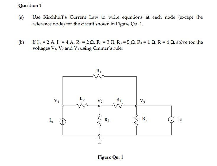
(a)
Use Kirchhoff's Current Law to write equations at each node (except the
reference node) for the circuit shown in Figure Qu. 1.
If IA = 2 A, IB = 4 A, R1 = 2 Q, R2 = 3 Q, R3 = 5 Q, R4 = 1 Q, R3= 4 Q, solve for the
(b)
voltages V1, V2 and V3 using Cramer's rule.
R1
Vị
R2
V2
R4
V3
R3
R5
IB
IA
Figure Qu. 1
Expert Solution
This question has been solved!
Explore an expertly crafted, step-by-step solution for a thorough understanding of key concepts.

This is a popular solution!

Trending now
This is a popular solution!

Step by step
Solved in 5 steps with 5 images

Knowledge Booster


Learn more about
Need a deep-dive on the concept behind this application? Look no further. Learn more about this topic, electrical-engineering and related others by exploring similar questions and additional content below.Recommended textbooks for you
Power System Analysis and Design (MindTap Course …
Electrical Engineering
ISBN:
9781305632134
Author:
J. Duncan Glover, Thomas Overbye, Mulukutla S. Sarma
Publisher:
Cengage Learning
Power System Analysis and Design (MindTap Course …
Electrical Engineering
ISBN:
9781305632134
Author:
J. Duncan Glover, Thomas Overbye, Mulukutla S. Sarma
Publisher:
Cengage Learning