Question 1 The two capacitors having their respective capacitances are connected as shown in figure from some time and obtained the voltages of V₁-8V and V2-12V. The value of the unknown capacitor (in mF) will be C₁ C₂=3mF Black Box
Q: 3) Given the circuit with an AC sinusoidal current source and an AC sinusoidal voltage source: ZR1…
A:
Q: A step-down transformer is rated 15kVA, 8000/200 and has the following equivalent circuit…
A: In this question we need to find the transformer winding impedance referred to high voltage side ,…
Q: (cs) -4000 30 ² +900S + 300 R().
A:
Q: 2: Draw the following signal. S(t) = 4 sin (277t+3m/2)
A: 2) Given S(t) = 4 sin[2π7t+(3π/2)].........(1) We need to draw the signal S(t)
Q: Draw the following signal. S(t) = 4 sin (2π7t+3π/2)
A: Here a signal is given S(t)=4sin(2.pi.7t+3pi/2) here amplitude =4 Frequency =7 Hz phase shift=3pi/2
Q: A 0.48520λ0 dipole antenna is made to work at 4 GHz. The antenna is then connected to a 12 V voltage…
A:
Q: 4) Find the Norton equivalent with respect to the terminals a and b for the circuit. 1500 250 02 www…
A:
Q: ауа А здокаже, 5 ир, 208V, 4- pole, бона, Дм Subjected to No-load test at 60 Hz and The results was:…
A:
Q: CCI VDD=15 V RG=5 MQ ww RD = 10 k Cc2 Vo R₁ = 5kQ
A:
Q: C i) What is the difference between a proximity sensor and a limit switch? ii) State 3 types of…
A:
Q: MI (+) • GG HAM 10 HWAM امد 671 ANAW 11 MAAN
A:
Q: A usual model that pops out in engineering involves the response of a system to an external force.…
A:
Q: 6.1 Given V = 5x³y'z and e = 2.258,, find (a) E at point P(-3, 1, 2), (b) p, at P.
A: We need to find out the electric field and volume charge density for given potential .
Q: Question 9 How many break-way (break-in and break-out) points a system with the following rootlocus…
A:
Q: 2. Calculate the current passing thru R5 R1 V1 -12V 1002 R4 m R5 1002 R2 1002 R3
A:
Q: 3) Find the Thevenin equivalent with respect to the terminals a and b for the circuit in the figure.
A: The thevenin's equivalent circuit can be obtained by calculating the open circuit voltage and…
Q: 6- If x(n) = {1 2 -1 3 0},h(n) = {3 0 - 1}, Find out convolution of two sequences given above.
A: In the given questions we need to calculate the convolution of the given function x(n) and h(n).
Q: In the CDMA system, what is the stage which adds the information symbol on the carrier (A)…
A: To find: In the CDMA system, what is the stage which adds the information symbol on the carrier.
Q: x[n] = given the system sin πη ; h[n] = Plot the spectrum of g[n]. x[n] sin πη .h[n] .g[n]
A:
Q: 1.1 Using the formula dv/dt approximate the slope of CT Answer: Vi vdc=1.8V 13 idc-Su A vd vd pr 010…
A:
Q: 30. Sketch v, for the network of Fig. 2.153 and determine the de voltage available. 100 V h -100 V…
A: For the given FWR sketch v0 and DC voltage at output available. As given diodes are ideal so,…
Q: 17-11 The thinnest copper wire normally manu- factured has a radius of 4 x 10⁻⁵ m. Find the…
A:
Q: The current through the inductor of the figure is known, Calculate the voltage v(t) Report only the…
A: Given: The current in the circuit, it=-5t+10 A. Inductance, L=5 mH.
Q: I. Simplify the logic function given by f = {(1, 3, 7, 12, 13, 14, 15, 8, 9, 10) with the DON'T CARE…
A:
Q: The female terminals are typically located in which connector half? O Clip O Cap O Receptacle O Plug
A: Plug used to connect with the socket. The female connector is generally a receptacle that receives…
Q: The circuit shown in the figure below is a O Low pass filter O High pass filter O Band pass filter O…
A: Given circuit:
Q: An overhead transmission line conductor is subjected to a horizontal wind load of 1.78 kg/m and a…
A:
Q: an explanation of the function of a flip-flop circuit and how it may be utilised Is the circuit…
A: Flip flop is a edge triggered circuit . Flipflops takes the inputs and gives the output only at the…
Q: a. What is the DC gain of this amplifier? (in dB) b. Where is the input pole frequency located? (in…
A:
Q: A non-inductive resistance at 15 ohms in series with a condenser takes 5A from 220V mains. What…
A:
Q: 12. If a circuit has a resistance of 1 megohm (1 million ohms), a capacitance of 2 uF (0.000002…
A: Given: In a circuit has, Resistance, R=1 MΩ. Capacitance, C=2 μF.
Q: 3. y''+a²y=0; y(0)= 1,y'(0)= 0.
A:
Q: One DC separately excited motor with rated data of PN-3kW, n =1500r/min, UN-110V, n=0.91, Ra=0.892.…
A:
Q: The conversion resolution in ADC or DAC is depending upon: O The input voltage and the number of…
A: The conversion resolution in ADC or DAC is depending upon: a) The input voltage and the number of…
Q: 15) An alarm sounds when certain conditions occur in a nuclear reactor. The output X, of a logic…
A: Given: Output of logic circuit is 1 only: Either CO2 pressure is too low and temperature is <=…
Q: 2. Find the closed-loop transfer function Y(s)/X(s) of the system shown below using block diagram…
A:
Q: Design a three ip amp instrumentation amplifier having gain 20.
A: Instrumentation amplifier This amplifier works the same as a regular amplifier just to amplify the…
Q: Answer the questions for the circuits given in the figure. +5V R1 2.50ΚΩ I'D D1 Vo
A: Given: In this question, the given details are, The given circuit diagram is, To find the value of…
Q: 24 V V1 www 1+ 12 V V2 V3 +1 10 V
A:
Q: A galvanometer with a full scale current of 10 mA has a resistance of 1000 Ω. The multiplying power…
A: Given: A galvanometer with a full scale current, Im = 10 mA. Meter resistance, Rm=1000 Ω Shunt…
Q: 9. Determine V₁, and Vo, for the networks of Fig. 2.138. +12 Vo Si 4.7 k www (a) Si Voy -10 Vo Si Si…
A:
Q: 1. What type of motors are used for conveyor system? Explain the operation of the conveyor system…
A: Conveyor system A conveyor system is a quick and efficient mechanical handling device that…
Q: Write the function in terms of unit step functions. Find the Laplace transform of the given…
A: In this question We need to write the given function in the term of step function and Laplace…
Q: 1 s² (s+12) 5(s+1) S+5 ((s)
A:
Q: What are the methods of triggering impulse voltage?
A: Triggering refers to the SCR's process of turning on. Triggering, then, is the process of moving the…
Q: A 600 KVA, 6600/400 Volts, 50 Hz, 3-phase, core type transformer has the following data Width of LV…
A:
Q: Design the state feedback controller so that G(s) is %OS-10% of the system and the settling time…
A: Given data Overshoot percentage, %Mp=10% Settling time, Ts=1 sec Open loop tarnsfer function (OLTF),…
Q: A GENERATING STATION HAS THE FOLLOWING DATA: INSTALLED CAPACITY = 300 MW ; CAPACITY FACTOR = 50%;…
A:
Q: b) What are the bit size and the output resolution for a Digital-to-Analog Converter with a…
A:
Q: The single-line diagram of a simple three-phase balanced power system with the components ratings is…
A: Since, We know that the base power remains the constant throughout the network. Therefore for all…
M & Tellegen's theorem-
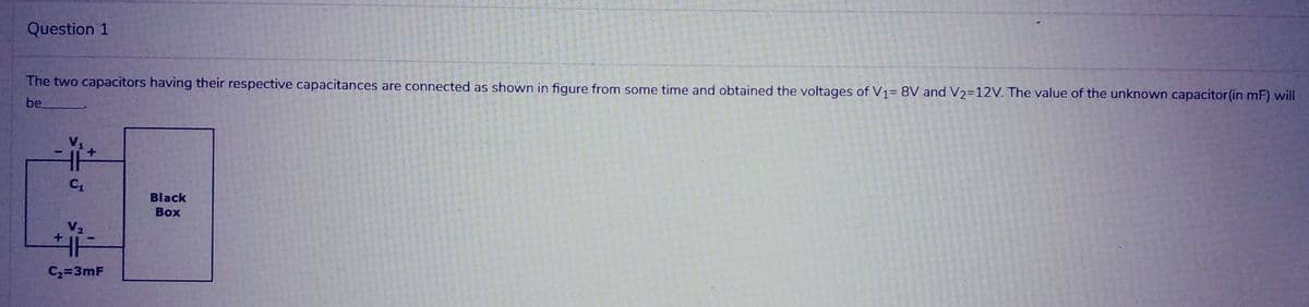
Step by step
Solved in 2 steps
- Three capacitors having capacitance values of 20F,40F, and 50F are connected in parallel to a 60 - Hz power line. An ammeter indicates a circuit current of 8.6 amperes. How much current is flowing through the 40F capacitor?You are an electrician working in an industrial plant. You discover that the problem with a certain machine is a defective capacitor. The capacitor is connected to a 240-volt AC circuit. The information on the capacitor reveals that it has a capacitance value of 10 mF and a voltage rating of 240 VAC. The only 10-mF AC capacitor in the storeroom is marked with a voltage rating of 350 WVDC. Can this capacitor be used to replace the defective capacitor? Explain your answer.An AC circuit contains a 24 resistor, a 15.9-mH inductor, and a 13.3F capacitor connected in parallel. The circuit is connected to a 240-V, 400-Hz power supply. Find the following values. XL=XC=IR=AIL=AIC=AP=WVARsL=VARsC=IT=AVA=PF=%=
- I have a series circuit with a source of 50V, resistor 400 ohms, capacitor Xc=120 ohms, and a 60 Hz. frequency, I'm looking to find out the Capacitance on the circuit, and the formula to solve the problem, Thanks.In the given series-parallel combination of capacitors, find the total capacitance, the total charge, the individual charges, and individual voltages. The capacitance of each capacitor is given in the diagram. The combination is connected to a power source of 100 V.Three capacitors each of the capacitance C are given. The resultant capacitance 2/3 C Can be obtained by using them ? a)Two in parallel and third in series with this combination b)All in parallel c)All in series d)Two in series and third in parallel across this combination
- Two capacitors give an equivalent capacitance of 9.00 pF when connected in parallel and an equivalent capacitance of 2.00 pF when connected in series. a.) What is the capacitance of each capacitor? b.) John was asked to design a capacitor in which small size and large capacitance were required. He said that he can achieve that by inserting a piece of paper between the plates. Do you agree with him? Why? Is there anything else that could be done to increase the capacitance?An emf source with E=100 V, a resistor with R=80 ohms, and a capacitance with C=4 uF are in series.connected. While the current is 0.9A during the loading of the capacitor, the load on the plates of the capacitor ishow big is it (in uC)?You measure the capacitanceC1of a capacitor by doing thefollowing: First connect capacitorsC1andC2in series to a power sup-ply that provides a voltageVthat can be varied. The capacitance ofC2is known to be3.00mF. Then vary the applied voltageV, and for eachvalue ofVmeasure the voltageV2acrossC2. After plotting your data asV2versusV, you find that the data fall close to a straight line that hasslope 0.650. What is the capacitanceC1?
- Derive the equivalent circuit for a parallel connection of ideal capacitors. Assume that the initial voltage across the paralleled capacitors is v(t0). (Hint: Sum the currents into the string of capacitors, recognizing that the parallel connection forces the voltage across each capacitor to be the same.)A resistor of R = 50Ω resistance is in series with a capacitor of C = 150μF. At t= 0, it is suddenly connected to a source of dc voltage of 25V. Determine the current in the circuit at any time t. Determine the current and the voltages across each element at t = 2τ.Acertain electric circuit has a resistor and a capacitor. The capacitor is initially charged to 100 V. When the power supply is detached, the capacitor voltage decays with time, as the following data table shows. Find a functional description of the capacitor voltage v as a function of time t. Plot the function and the data on the same plot.