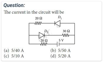
Question: The current in the circuit will be D₁ (a) 5/40 A (c) 5/10 A 20 2 www 20 2 www 30 Ω www 5V (b) 5/50 A (d) 5/20 A


Q: 1- What is the transducer and what is used for? 2 What is the difference between temperature…
A: The importance of the transducer needs to be explained and the difference between the temperature…
Q: 3. For the network shown in the following figure, find V0 using the following analysis techniques:…
A: here we have to find the voltage V0 by using mesh analysis and superposition theorem
Q: Using the principle of superposition, calculate the current through the 50 ohm resistor in the…
A: For the given circuit the value of the current flowing through the 50ohm resistor needs to be…
Q: A 480 V, 50 Hz, Y-connected, 4 pole synchronous generator has the OCC shown in the figure 1 below.…
A: Since the question posted by you has multiple sub-parts, we will solve the first three sub-parts for…
Q: Illustrate the basic concept of standard amplitude modulation
A: Amplitude modulation is the technique of modulation where the amplitude of the carrier signal…
Q: For the signal v(t) = 15 cos(2π225t + π/3) + 10 cos(2π475t + π/2) + 2 sin(2π650t + π/7), if you…
A: Given: v(t) = 15 cos(2π225t + π/3) + 10 cos(2π475t + π/2) + 2 sin(2π650t + π/7) Sampling frequency…
Q: The step response of an LTI systems is given as s(n) = ()-2u(n + 2) Determine the system function…
A: Here the given problem is from signals and systems. The matched solution is of different problem so…
Q: I want a formula that combines current with area with capacitance, with an example of a solution
A: The formula that combines current (I), area (A), and capacitance (C) is given by: Q=∫0tI.dt --(1)…
Q: Determine the inverse Laplace transform of -5760 e-s G(s) 87 Note: You must use the notation u(t -…
A:
Q: 1) Find the value of Vx. W 24V W 1.2 L W 502 W 400 105
A: NOTE: As per our company guidelines we are supposed to answer only one question. Kindly repost other…
Q: For the circuit attached, A. Determine V0 using superposition. B. Confirm your results using Node…
A: The voltage vo needs to be calculated in the given circuit by using the superposition theorem and…
Q: 5. Find the output voltage V (t) in the circuit shown. 58 3 A 592 X t=0 ww 10 92 4H10 mF + Vo 2.8
A: The circuit diagram,
Q: 1. Consider an ideal Op-Amp with the inputs of v₁ = 0 V and V12 = 5 V. Label voltages and currents…
A: For the given operational amplifier circuit the value of the voltage at every node needs to be…
Q: 5 mW 8 dB 3 dB OA. 31 mW OB. 0.31 mW OC. 3.1 mW O D. 310 mW 08 18. In the circuit shown in the…
A: given circuit is power input to the first part of the circuit is - Pi power…
Q: Consider the system illustrated below. Suppose the following experiments are run: • When a 20 Ohm…
A: In this question we need to find the Thevenin equivalent of the given circuit.
Q: Find the currents I₁, I2 and 13 in the following circuit using: Gaussian elimination 414 b. Cramer's…
A: here we have to find the currents I1 , I2 , I3 using gaussian elimination and crammer's rule.
Q: he no load output voltage of a certain zener diode regulator is 9.23 V and the full load output is…
A: The load regulation of a zener diode regulator is expressed as the percentage change in output…
Q: If f (z,t) the wave equation is f(z,t) = 10 cos (30 z - 50 t) in cm Then the the wave is wavelength…
A: Function is given as, fz,t=10cos30z-50πt.
Q: 10A ↑ Click here for image | R1 Ω R2 R3 Ω In this circuit R1 = 1/5.00, R2 = 1/2.00 and R3 = 1/10.00,…
A:
Q: Stability via Reverse Coefficients T(s) = 10 s5 +254 + 3s3 + 6s² + 5s + 3
A: Given here a transfer function and asked to find the stability via Reverse Coefficients.
Q: The Fourier transform of a signal h(t) is H(jw) = (2 cos w) (sin 2w)/w. The value of h(0) is
A: Hjω=2cosωsin2ωω
Q: Find the total power developed in the circuit in below figure if vo = 10 V? 9A 20 V(+ DO 6A+ + Va -…
A: v0 = 10 V Pdev = ?
Q: Draw the circuit diagram an solve using ohms law 1. A lamp is rated 100 watts , 200 V. Find the hot…
A: Voltage source V = 200 V. Power of lamp P = 100 W.
Q: Problem11. (a) Design a Lead-Lag Compensator whose general expression is given below for the…
A:
Q: 35. Data for a mine are as follows: Estimated probable output = 20,000 tons annually Time to exhaust…
A: Data for a mine are as follows, Estimated probable output = 20,000 tons annually Time to exhaust…
Q: Q17. The load impedance that will absorb the maximum average power in the following circuit is: A)…
A: “Since you have posted multiple questions, we will provide the solution only to the first question…
Q: Q1) The equivalent low-side parameters -0.00920 52 and X eq transformer are R eq.IS operated in the…
A: Given,For a low-side transformer,S=250kVAVload=4160 VV=480Vf=60HzReq,LS=0.00920 ΩXeq, LS=0.0433…
Q: Obtain the transfer function G(s) whose response curve to an amplitude step=1 Amplitude 50 45 40 10…
A: The above question is based on the determination of the transfer function from the step response of…
Q: 5. A three-phase rectification system has a voltage ripple of 14%. If the output kVp is 150, what is…
A: Given data, Output voltage VO=150 V. Ripple voltage Vr=14 %.
Q: QUESTION B A long vertical wire le partially placed in a uniform magnetic field B-53 mT. The B-field…
A: Solution: Given Data: B=53 mT θ=36° Electrical Current (I)=3.7A L=71cm Determine : here find…
Q: Aim: Determination of ABCD paratmeters for long transmission line with a given condition and hence…
A: Voltage rating 550 kV, The series impedance of the line…
Q: Question 1. Suppose that a de motor driving a conveyor band has the transfer function of G(S)…
A: (a) To find the time function of angular displacement, θ(t), we need to perform inverse Laplace…
Q: In the circuit given below, V=4 kV, X=2 , R=1 , and f=50 Hz. Determine 9 SW1=0 e(t) = V2V cos(at +…
A: Voltage V=4 KV = 4000 V. Inductive reactance X=2 Ω. Resistance R=1 Ω. Frequency f = 50 Hz. Circuit…
Q: Q5: A: 1- What is the transducer and what is used for?
A: Transducer is a device which converts one form of energy into another form. In many applications a…
Q: 5. How many poles are in the right half-plane for the open-loop system of Figure P6.1? [Section:…
A: The open loop system is,
Q: j1Ω 42 www ਨਵੀਂ 60/90°V(+ 1₁ j8 2 · j5 2 12 + 10 2
A: here we have to find the currents I1 , I2 and voltage V0 using mesh analysis.
Q: Q5: A: 1- What is the transducer and what is used for? 2 What is the difference between temperature…
A: The importance of the transducer needs to be explained and the difference between the temperature…
Q: A layer of dielectric with a refractive index of 1.64 is deposited on the surface of a GaAs…
A:
Q: Calculate the RMS value of the following function v (t) MAA 4 6 2 -1 2 8 110 t
A: it is asked to find the rms value of given waveform
Q: Often, pumps and some other electrical equipment are measured in horsepower. It is highly…
A: given that motor power rating (P) is 10 HP 1HP = 746 Watts motor runs 2.5 hours (t - time) a day…
Q: Let D = 2pz'a, + p cos² a. Evaluate (a) f, D.ds (b) , V. Dav over the region defined by 2 ≤ p ≤ 5,…
A:
Q: Q16: A modulating signal f(t) is bandlimited to 4KHz is sampled at a rate of 10.000 samples/ sec.…
A: Given data: Modulation frequency fs= 4 KHz Sampling rate fs= 10,000 samples/s Quantized level L=…
Q: Q5: A: 3-Set three types of transducers based on quantity to be measured
A: Transducer is a device that converts one form of energy into another form of energy. Transducers are…
Q: Determine the simplest expression for the convolution of the two signals. x3[n] = (†)"u[n] _x4[n] =…
A:
Q: Determine the simplest expression for the convolution of the two signals. x3[n] = (₂2)"u[n]_x4[n] =…
A:
Q: B: Tikrit University has been established its electrical distribution system in a special method…
A: VA=230 Volts,VB=225 Volts.
Q: The two coupled inductors in the figure are connected in a circuit with the voltages and currents…
A: here we have to find the voltages V1 , V2 we know that voltage across the inductor is VL=Ldidt
Q: Q1. Find the current through each resistor and voltage drop at each resistor for the networks in…
A:
Q: A 220 V, 15 kW, 850 r.p.m. shunt motor draws 72.2 A when operating at rated condition. The…
A: I have written this solution as handwritten solution. Hope you find the perfect solution.
Q: Q1. Find the current through each resistor and voltage drop at each resistor for the networks in…
A:

Step by step
Solved in 3 steps with 2 images


- Incandescent lighting of 500 W is connected in parallel with an inductive load. A clamp-on ammeter reveals a total circuit current of 7 A. What is the inductance of the load connected in parallel with the incandescent lights? Assume a voltage of 120 V and a frequency of 60 Hz.A current source in a linear circuit has is = 10 cos(460πt - 32o) A. Calculate is at t = 5 ms. Round your answer to 2 decimal places.My Answer here is -0.2727 A Please verify my answer
- A series RL circuit in which R=5 ohms and L=20 mH has an applied voltage e=100+50sinwt+25sin3wt with w=500 radians per sec. Determine the power dissipated in the resistor of the circuit.The current in the circuit shown is known to be io=5e−2000t(2cos 4000t+sin 4000t) for t≥0+. Find v1(0+) and v2(0+).A series circuit has a total resistance of 19 ohms and a current flow of 12 A. What is the applied voltage? Select one: a. 1.583 b. .631 c. 228 d. 410
- this circuit Flows to 20 amper then plot v(t) ia(t)Find the current in the RLC circuit, assuming that E(t) = 0 for t > 0 R = 4 ohms; L = .05 henrys; C = .008 farads; Q0 = -1 coulombs; I0 = 2 amperes I need help8. 7.8 In the circuit the voltage and current expressions are v=400e−5tV, t≥0+;i=10e−5tA, t≥0.3. c) L.
- 10. 7.44 PSPICEMULTISIM The switch in the circuit hasbeen open a long time before closing at t=0. Find vo(t) for t≥0+.8. 7.8 In the circuit , the voltage and current expressions are v=400e−5tV, t≥0+;i=10e−5tA, t≥0.2. b) τ (in milliseconds).The voltage and current at the terminals of the circuit element are zero for t<0. For t≥0 they are v=50e−1600t−50e−400t V,i=5e−1600t−5e−400t mA. How much energy is delivered to the circuit element between 0and 625 μs?