QUESTIONS:- 1- Conclusions from experience ? 2-write any five parts of a wind turbine ?
QUESTIONS:- 1- Conclusions from experience ? 2-write any five parts of a wind turbine ?

Introductory Circuit Analysis (13th Edition)
13th Edition
ISBN:9780133923605
Author:Robert L. Boylestad
Publisher:Robert L. Boylestad
Chapter1: Introduction
Section: Chapter Questions
Problem 1P: Visit your local library (at school or home) and describe the extent to which it provides literature...

Related questions

Concept explainers
Synchronous Generator
In comparison to an asynchronous generator, it is a machine where the rotor speed is equal to the rotating magnetic field produced by the stator, i.e., mechanical speed is equal to the electrical speed, thus called synchronous, and not asynchronous.
Salient Pole Rotor
Salient pole rotor includes a large number of exposed poles mounted on a magnetic wheel. The construction of a bright pole is as shown in the image on the left. The proposed poles are made of metal laminations. The rotor winding is provided on these poles and is supported by pole shoes.
Question
QUESTIONS:-
1- Conclusions from experience ?
2-write any five parts of a wind turbine ?
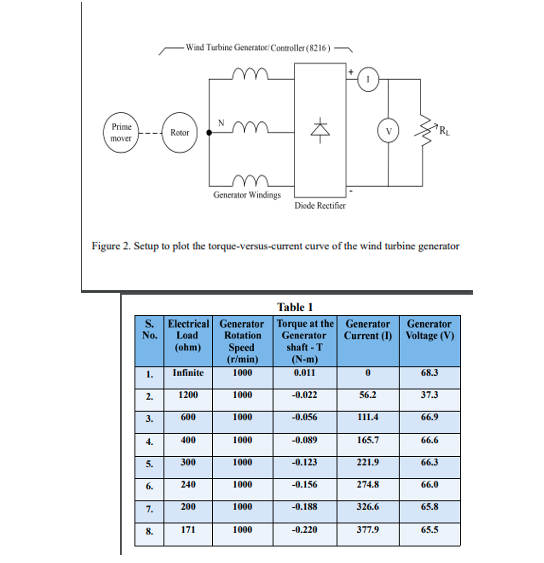
Transcribed Image Text:Wind Turbine Generator Controller (8216)
Prime
Rotor
mover
Generator Windings
Diode Rectifier
Figure 2. Setup to plot the torque-versus-current curve of the wind turbine generator
Table 1
Electrical Generator
Load
(ohm)
Torque at the Generator
Generator
shaft -T
(N-m)
S.
No.
Generator
Current (I) Voltage (V)
Rotation
Speed
(r/min)
1.
Infinite
1000
0.011
68.3
2.
1200
1000
-0.022
56.2
37.3
3.
600
1000
-0.056
111.4
66.9
4.
400
1000
-0.089
165.7
66.6
5.
300
1000
-0.123
221.9
66.3
6.
240
1000
-0.156
274.8
66.0
7.
200
1000
-0.188
326.6
65.8
8.
171
1000
-0.220
377.9
65.5
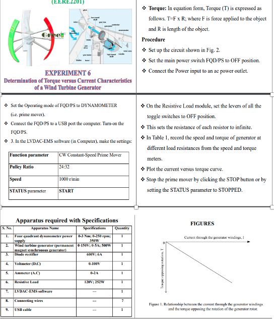
Transcribed Image Text:(EEREZ201)
* Torque: In equation form, Torque (T) is expressed as
follows. T=F x R; where F is force applied to the object
and R is length of the object.
Greef
Procedure
* Set up the circuit shown in Fig. 2.
* Set the main power switch FQD/PS to OFF position.
* Connect the Power input to an ac power outlet.
EXPERIMENT 6
Determination of Torque versus Current Characteristics
of a Wind Turbine Generator
• Set the Operating mode of FQD/PS to DYNAMOMETER
(ic. prime mover).
* On the Resistive Load module, set the levers of all the
toggle switches to OFF position.
• Connect the FQD PS to a USB port the computer. Tum-on the
* This sets the resistance of each resistor to infinite.
FQD PS.
* In Table 1, record the speed and torque of generator at
• 3. In the LVDAC-EMS software (in Computer), make the settings:
different load resistances from the speed and torque
Function parameter
CW Constant-Speed Prime Mover
meters.
Pulley Ratio
24:32
* Plot the current versus torque curve.
Speed
• Stop the prime mover by clicking the STOP button or by
1000 r'min
STATUS parameter
START
setting the STATUS parameter to STOPPED.
Apparatus required with Specifications
FIGURES
5. No.
Apparatus Name
Specifications
Quantity
03 Nm; 0-250 rpm;
Four quadrant dynanometer power
supply
Wind turbine generator (permanent 150V; 0-5A; 500W
1.
Curent through the generator windings, I
350W
1
magaet synchronous generator)
Diode rectifier
3.
600V; 6A
4.
Voltmeter (DC)
0-100V
1
5.
Ammeter (A.C)
0-2A
6.
Resistive Load
120V; 252W
7.
LVDAC-EMS seftware
&.
Connecting wires
Figure 1. Relaticnship between the curent through the generater windings
and the torque opposing the rotation of the generator rotor.
9.
USB cable
1
1vomoesodda anban
Expert Solution
This question has been solved!
Explore an expertly crafted, step-by-step solution for a thorough understanding of key concepts.

Step by step
Solved in 3 steps with 2 images

Knowledge Booster


Learn more about
Need a deep-dive on the concept behind this application? Look no further. Learn more about this topic, electrical-engineering and related others by exploring similar questions and additional content below.Recommended textbooks for you
Introductory Circuit Analysis (13th Edition)
Electrical Engineering
ISBN:
9780133923605
Author:
Robert L. Boylestad
Publisher:
PEARSON

Delmar's Standard Textbook Of Electricity
Electrical Engineering
ISBN:
9781337900348
Author:
Stephen L. Herman
Publisher:
Cengage Learning

Programmable Logic Controllers
Electrical Engineering
ISBN:
9780073373843
Author:
Frank D. Petruzella
Publisher:
McGraw-Hill Education
Introductory Circuit Analysis (13th Edition)
Electrical Engineering
ISBN:
9780133923605
Author:
Robert L. Boylestad
Publisher:
PEARSON
Delmar's Standard Textbook Of Electricity
Electrical Engineering
ISBN:
9781337900348
Author:
Stephen L. Herman
Publisher:
Cengage Learning
Programmable Logic Controllers
Electrical Engineering
ISBN:
9780073373843
Author:
Frank D. Petruzella
Publisher:
McGraw-Hill Education

Fundamentals of Electric Circuits
Electrical Engineering
ISBN:
9780078028229
Author:
Charles K Alexander, Matthew Sadiku
Publisher:
McGraw-Hill Education

Electric Circuits. (11th Edition)
Electrical Engineering
ISBN:
9780134746968
Author:
James W. Nilsson, Susan Riedel
Publisher:
PEARSON

Engineering Electromagnetics
Electrical Engineering
ISBN:
9780078028151
Author:
Hayt, William H. (william Hart), Jr, BUCK, John A.
Publisher:
Mcgraw-hill Education,