QUESTIONS What type of electronic device is required for amplitude modulation? 1. the result if we remove positive half of the AM signal instead of its n
QUESTIONS What type of electronic device is required for amplitude modulation? 1. the result if we remove positive half of the AM signal instead of its n

Introductory Circuit Analysis (13th Edition)
13th Edition
ISBN:9780133923605
Author:Robert L. Boylestad
Publisher:Robert L. Boylestad
Chapter1: Introduction
Section: Chapter Questions
Problem 1P: Visit your local library (at school or home) and describe the extent to which it provides literature...

Related questions

Question
Transcribed Image Text:40501 - Amplitude Modulation and Demodulation
6/6
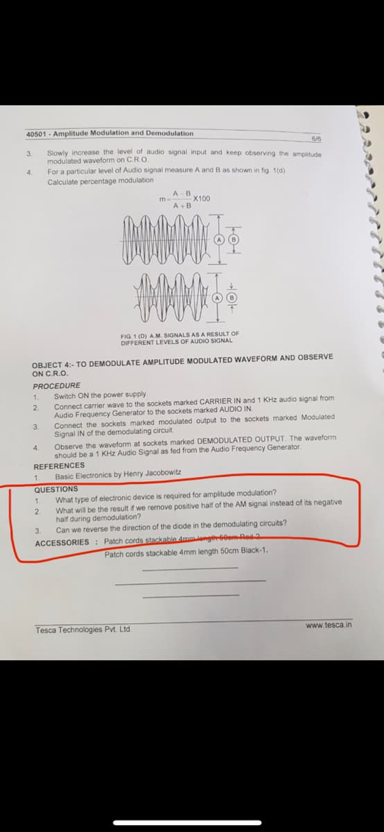
Slowly increase the level of audio signal input and keep observing the amplitude
3.
modulated waveform on C.R.O
For a particular level of Audio signal measure A and B as shown in fig. 1(d)
4.
Calculate percentage modulation
A-B
X100
m
A +B
FIG 1 (D) AM. SIGNALS AS A RESULT OF
DIFFERENT LEVELS OF AUDIO SIGNAL
OBJECT 4:- TO DEMODULATE AMPLITUDE MODULATED WAVEFORM AND OBSERVE
ON C.R.O.
PROCEDURE
Switch ON the power supply
Connect carrier wave to the sockets marked CARRIER IN and 1 KHz audio signal from
Audio Frequency Generator to the sockets marked AUDIO IN.
1.
Connect the sockets marked modulated output to the sockets marked Modulated
Signal IN of the demodulating circuit.
3.
Observe the waveform at sockets marked DEMODULATED OUTPUT. The waveform
should be a 1 KHz Audio Signal as fed from the Audio Frequency Generator.
4.
REFERENCES
1.
Basic Electronics by Henry Jacobowitz
QUESTIONS
What type of electronic device is required for amplitude modulation?
What will be the result if we remove positive half of the AM signal instead of its negative
half during demodulation?
Can we reverse the direction of the diode in the demodulating circuits?
1.
2.
ACCESSORIES : Patch cords stackable Ammengi60em-Red2
Patch cords stackable 4mm length 50cm Black-1.
Tesca Technologies Pvt. Ltd.
www.tesca.in
Expert Solution
This question has been solved!
Explore an expertly crafted, step-by-step solution for a thorough understanding of key concepts.

This is a popular solution!

Trending now
This is a popular solution!

Step by step
Solved in 2 steps

Knowledge Booster


Learn more about
Need a deep-dive on the concept behind this application? Look no further. Learn more about this topic, electrical-engineering and related others by exploring similar questions and additional content below.Recommended textbooks for you
Introductory Circuit Analysis (13th Edition)
Electrical Engineering
ISBN:
9780133923605
Author:
Robert L. Boylestad
Publisher:
PEARSON

Delmar's Standard Textbook Of Electricity
Electrical Engineering
ISBN:
9781337900348
Author:
Stephen L. Herman
Publisher:
Cengage Learning

Programmable Logic Controllers
Electrical Engineering
ISBN:
9780073373843
Author:
Frank D. Petruzella
Publisher:
McGraw-Hill Education
Introductory Circuit Analysis (13th Edition)
Electrical Engineering
ISBN:
9780133923605
Author:
Robert L. Boylestad
Publisher:
PEARSON
Delmar's Standard Textbook Of Electricity
Electrical Engineering
ISBN:
9781337900348
Author:
Stephen L. Herman
Publisher:
Cengage Learning
Programmable Logic Controllers
Electrical Engineering
ISBN:
9780073373843
Author:
Frank D. Petruzella
Publisher:
McGraw-Hill Education

Fundamentals of Electric Circuits
Electrical Engineering
ISBN:
9780078028229
Author:
Charles K Alexander, Matthew Sadiku
Publisher:
McGraw-Hill Education

Electric Circuits. (11th Edition)
Electrical Engineering
ISBN:
9780134746968
Author:
James W. Nilsson, Susan Riedel
Publisher:
PEARSON

Engineering Electromagnetics
Electrical Engineering
ISBN:
9780078028151
Author:
Hayt, William H. (william Hart), Jr, BUCK, John A.
Publisher:
Mcgraw-hill Education,