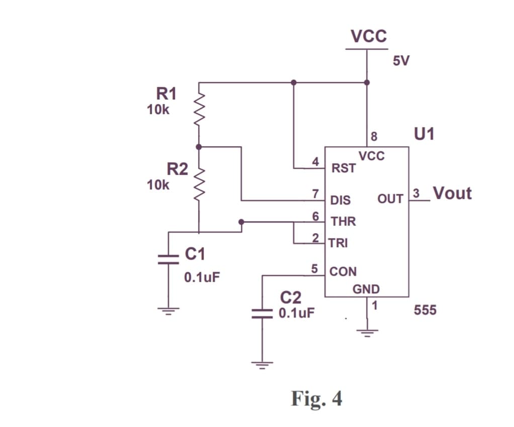
R1 10k R2 10k www C1 0.1uF 4 7 6 2 C2 0.1uF VCC RST DIS THR TRI 5 CON Fig. 4 8 VCC 5V GND 1 U1 OUT 3 Vout 555


Q: Pre-Lab Problem Consider the electrical RC circuit shown in the illus- tration. The resistance R 10…
A:
Q: I would like to know the steps to solve the problem to get Equation 10.1.2 in detail, thank you in…
A:
Q: Consider the following baseband message signals m(t) = 500 exp(-100|t-0.51). For each of the (iv)…
A: Given:Baseband signals, we need to do:a) sketch the spectrum of m(t). b) sketch the spectrum of c)…
Q: For the circuit shown in the following figure, calculate the value of vc(0+), iL(0+), (0+) e iL(t)…
A: Given:we are required to find:
Q: Pre-Lab Problem Consider the electrical RC circuit shown in the illus- tration. The resistance R =…
A:
Q: Complete using the 2020 NEC, Table 310.16, 310.15(B)(1), and 310.15(C)(1) or 2023 NEC, Table 310.16,…
A: According to the question, we need to complete the given table using the 2020 NEC, Table 310.16,…
Q: 16.46 Develop the state equations for the circuit shown in Fig. 16.71. Figure 16 71 ΤΗ m 2 F 4902…
A: In this question, we need to determine the state equations of the given circuit. Here two…
Q: 252 M + vi(t) 0.1 F + 1H2v₁ (t) For the circuit shown, vi(t) = 10 u(-t) + 20 u(t). voltage v₁ (t) =
A:
Q: For each of the following 2nd order systems, find S, W 16 s² + 3s +16 T(s) = T(s) = 0.04 s² +0.02s…
A: For the given transfer function, the value of damping ratio, natural frequency, rise time, peak…
Q: True or False - x(t) and e(t - to) has the same energy distribution as a function of time if to > 0.…
A: The question is asking whether the energy distribution of a signal x(t) is the same as that of a…
Q: Needs Complete typed solution with 100 % accuracy.
A: The objective of the question is to design the layout of a minimum size NMOS transistor using 180 nm…
Q: Figure shows a transistor switching circuit. Find the Vcc and Rc, which causes the output voltage to…
A:
Q: transfer function: Ks² p2 [1+(s/0,1)][1+(s/0,2)][1+(s/0,,)]* K = 1/(2π)² (V/V)-s² fp₁ = = 100 Hz &…
A:
Q: Use superposition to determine the current through the 5 kn. I (+1 V1 30V R1 10k R2 5k I1 3m
A: The current flowing through the 5k ohm resistor is I=4mamps.Explanation:Step 1:SUPERPOSITION…
Q: For the circuit shown in the figure, the current io' due to the (3A) current source is: 4V 6 Ω Μ 8A…
A: According to questions, we need to find current io.
Q: H.W: For the network shown in figure below, determine : 1. The current I using ((KCL). 2. The source…
A:
Q: Consider a DSB-SC modulated wave using message signal m(t) with spectrum shown in the following…
A: Given:spectrum of mesaage signal m(t),m(t) is DSB-SC modulated with carrier . If DSB-SC signal is…
Q: 2. Use source transformation to find v, in the circuit below. 520 V 16 Ω 1Α 200 Ω Σ40 Ω 6Ω 4 Ω v.…
A:
Q: 5.4 The rectangular loop shown in Fig. P5.4 consists of 20 closely wrapped turns and is hinged along…
A: Given that,Number of turns, Current in windings, Plane angle, Magnetic field,
Q: (A)-Correct the false statements - It is not possible to increase the speed of a shunt DC motor…
A: In the given question we need to correct the false statements given in question.
Q: compute the deciaml indications for the given pulse tra
A: a. To convert the binary number 10100111 to decimal, you use the positional notation system where…
Q: Gas, 20 "WC S.G-0.88 S.G-1.03 40" 50" mA 110" for the above level system, if the transmitter is…
A: A transmitter is a device or system that generates and sends electromagnetic signals or waves,…
Q: 3. Given the information appearing in Fig. 4.13, determine the resistance R₂. FIG. 4.13 E + R₁ www…
A: According to questions we need to calculate resistance value R2.
Q: 30. Find and graph the frequency response of each of the circuits in Figure E.30 given the indicated…
A: "Since you have posted a question with multiple questions, we will provide the solution only to the…
Q: d²y dy For the LCCDE +2 dt² dt the impulse response h(t) = +y(t) = dx == dt + 2x(t),
A: The impulse response of the system needs to be determined for the given differential equation.
Q: Problem 4-4: The input signal F (t) = 2 + sin 15.7t + sin 160t Nis measured by a force measurement…
A: Given: The parameters of a second-order system are given as:natural frequency rad/s,damping ratio ,…
Q: Q6.1. Describe the phenomenon of guiding of a uniform plane wave by a pair of par- allel, plane,…
A: We need to describe the phenomenon of guiding of a uniform plane wave by a pair of parallel, plane,…
Q: 2. A boost converter has an output of 30V from 12 V source input during the Continuous Conduction…
A: Given data: -Vo=30 VVin=12 VL=120 μHRL=50 Ωfs=25 kHzAs per the guidelines I can answer only first 3…
Q: A 60 Hz source having and effective voltage of 120 V delivers an effective current of 15 A to a…
A: In this question, we need to determine the expression of the current and voltage in degree and…
Q: a) When the switch is closed in the circuit shown in Fig. below, the voltage on the capacitor is 10…
A: A capacitor is an electronic component used to store and release electrical energy in a circuit. It…
Q: Q 2) Find the Thevenin equivalent of the circuit at terminals a-b. 0.1io 40 92 + 10 Q2 20 Ω +501 b…
A: To calculate the value of VthRth of the given circuit
Q: H.W.(2) Determine the total conductance and resistance for the parallel network of Fig. shown below…
A: We need to determine the total conductance and resistance for the parallel network of Fig. shown…
Q: i1=5A i2=1A Vs=35V then find power dissipated in the below circuit
A: Given circuit,i1=5 A,i2=1 A,Vs=35 V.Asked to find the power dissipated in the circuit.
Q: i(t) Node 1 iR, (t) R₁ iz(t) 0000 L + C не Node 2 -ic(t) iR₂ (1) R₂ 4vz(t)
A: Electrical network:This is a network that has a closed path for current flow and comprises…
Q: Which of the following statements about a doubly-fed induction generator (DFIG) are true? Select one…
A: Answer(a) Doubly-fed induction generators (DFIGs) do not operate at a constant rotational speed…
Q: For the circuit in the figure, determine the response of i(t), valid for all t, if at t=0+, the…
A: An RLC circuit is excited by two sources: a 10 V constant voltage source and A current source.We…
Q: Consider the signal x[n] = cos(rn) + sin(n). (a) Find the DTFS coefficients of a[n]. (b) Plot (by…
A:
Q: Q(1)(B)-Correct the false statements 1- When c series de motor is operating without load, the…
A: DC Motor: A direct current motor is an electrical machine that transforms electrical energy into…
Q: which of the following band diagrams of a p-n junction is correct I why ? Consider equilibrium…
A:
Q: 1. Design an FSM to keep track of the mood of four students working in the digital design lab. Each…
A: 1. Number of Students and Moods:We have 4 students.Each student can have one of 5 moods: HAPPY,…
Q: A 3-phase, 3-wire balanced wye - connected load takes a line current of 30 A at a 0.7 pf lagging.…
A: Given,A 3- phase ,3 - wire balanced wye-connected load,line current IL=30 A,power factor ,Line…
Q: 12 V 1R3 IRI R1 V1 560 Q ww R3 1 ΚΩ. www R1 ¹R2 iR4 R22.1 k R42.1 kQ
A: Current is flow of electric charge through a conductor. It is typically measured in amperes (A) and…
Q: For each of the following transfer functions shown below, find the locations of poles and zeros,…
A: For the given system transfer function the location of poles, and zeros need to be identified and…
Q: Upon graduating from EEE, you took up a career with a wireless technology company. One of your…
A: The objective of the question is to determine the condition for h1 and h2 such that the performance…
Q: 1. (a) A non-contact electrode has a circuit model on the right with: i. zero half-cell potential…
A: Solution for question (1.a):The circuit model of a non-contact electrode is shown below.
Q: D. Make the frequency response graphs in MATLAB, include code. E. The Bode plot made in MATLAB,…
A: Given:a system with equation,we need to do:d) make the frequency response graphs in MATLAB,…
Q: Night has fallen and you’ve taken shelter in a room with 4 doors. You’ll need a good sleep so that…
A: Detailed answer shown belowExplanation: 1. Answering the questions:a) Minimum number of AA…
Q: Which of the following does the NEC recognize as a device? A) Light bulb B) Locknut C)…
A: The device recognised by NEC from the given set of elements needs to be identified.
Q: 21. Find Vi(jo) and V₂(jw) in terms of I₁ (jo) and I₂(jw) for each circuit of Fig. 13.49. + V₁ www…
A: Mutual inductance refers to the phenomenon where a change in current flowing through one coil…
Q: 6.34 ΜΑ νη - 12V R1 Μ 1 ΚΩ R5 1.5 ΚΩ R6 32.2ΚΩ
A:
If you apply 4V on pin 5 draw the waveform at each pin 2,3 on the same axis as the dual mode for the oscilloscope ,Comment on the waveform shape.

Unlock instant AI solutions
Tap the button
to generate a solution
Click the button to generate
a solution
- If R0= 44 milliohms and Ri= 736 ohms, what is R1 , R2, R3 in the equivalent circuit????For the circuit below if selection lines S2S1S0=011 the output Z will be ____, if S2S1S0=100, Z will be ____, if S2S1S0=001, Z will be ____.i want ans q 3these the ans for 1.2(1) https://www.bartleby.com/questions-and-answers/please-provide-calculation-with-brief-discusssion-and-explanation-in-your-solution.-1.-find-volt-in-/7ab4b23c-9640-4a81-a0d4-f4ec037a2eb8(2) https://www.bartleby.com/questions-and-answers/1.-find-volt-in-the-circuit-below-assuming-il0-0a.-percent3d-ww-90e-ut-v-2-h-ll/a3894d58-ee1a-47e2-b3da-973f4aa01991
- Suppose that we have an unusual type of FET for which iD=3 exp(vGS)+0.01vDS2 Here, iD is in mA, vGS is in volts, and vDS is in volts. Determine the values of gm and rd for a Q point of VGSQ=1 V and VDSQ = 10 V.Are the following statements correct or wrong? Justify your answer. (a) GTO requires very low current applied to its gate to be turn off. (b) IGBT is a voltage driven device. (c) BJT is more efficient than IGBT in high power applications. (d) Thyristors are used only for low voltage, low current applications. (e) MOSFETs are used for high frequency applications.Are the following statements correct or wrong? Justify your answer. (a) GTO requires very high current applied to its gate to be turn ofr. (b) IGBT is a current driven device. (c) IGBT is more efficient than BJT in high power applications. (d) Thyristors are used only for low voltage, low current applications. (e) MOSFETS are used for low frequency applications.
- Calculate: a) IDQ and VGSQ b) IDS c) IDA 12-bit counting converter with VFS = 5 V and fc = 1 MHz has an input voltage VX = 3.760 V. (a) What is the output code? What is the conversiontime TT for this value of VX if fc = 1 MHz? (b) Repeat for VX = 4.333 V.2. Given:VCC: 16 voltsRB1: 7000 ohmsRB2: 50 ohmsRB3: 50 ohmsRB4: 1500 ohmsB=beta: 100RE: 750 ohmsRC: 500 ohmsVCE: ? volts
- For this question : https://www.bartleby.com/questions-and-answers/i-need-a-circuit-that-will-do-normal-am-modulation-using-diode-switching-and-then-demodulate-it-enve/b8317fe9-a8b5-4b96-8fb7-1fb978c62717 I used the circuit in the provided photo And i got wrong values, the output should be the message signal but i got another ouput. I provided a photo after the circuit photo that shows the result in the time domain.Are the following statements correct or wrong? Justify your answer.(a) GTO requires very high current applied to its gate to be turn off.(b) IGBT is a current driven device.(c) IGBT is more efficient than BJT in high power applications.(d) Thyristors are used only for low voltage, low current applications.(e) MOSFETs are used for low frequency applications. (I got the answer in the search but if possible,i want it in a slightly different way)What values of β correspond to α = 0.970, 0.993, 0.250? (b) What values of αcorrespond to β = 40, 200, 3?