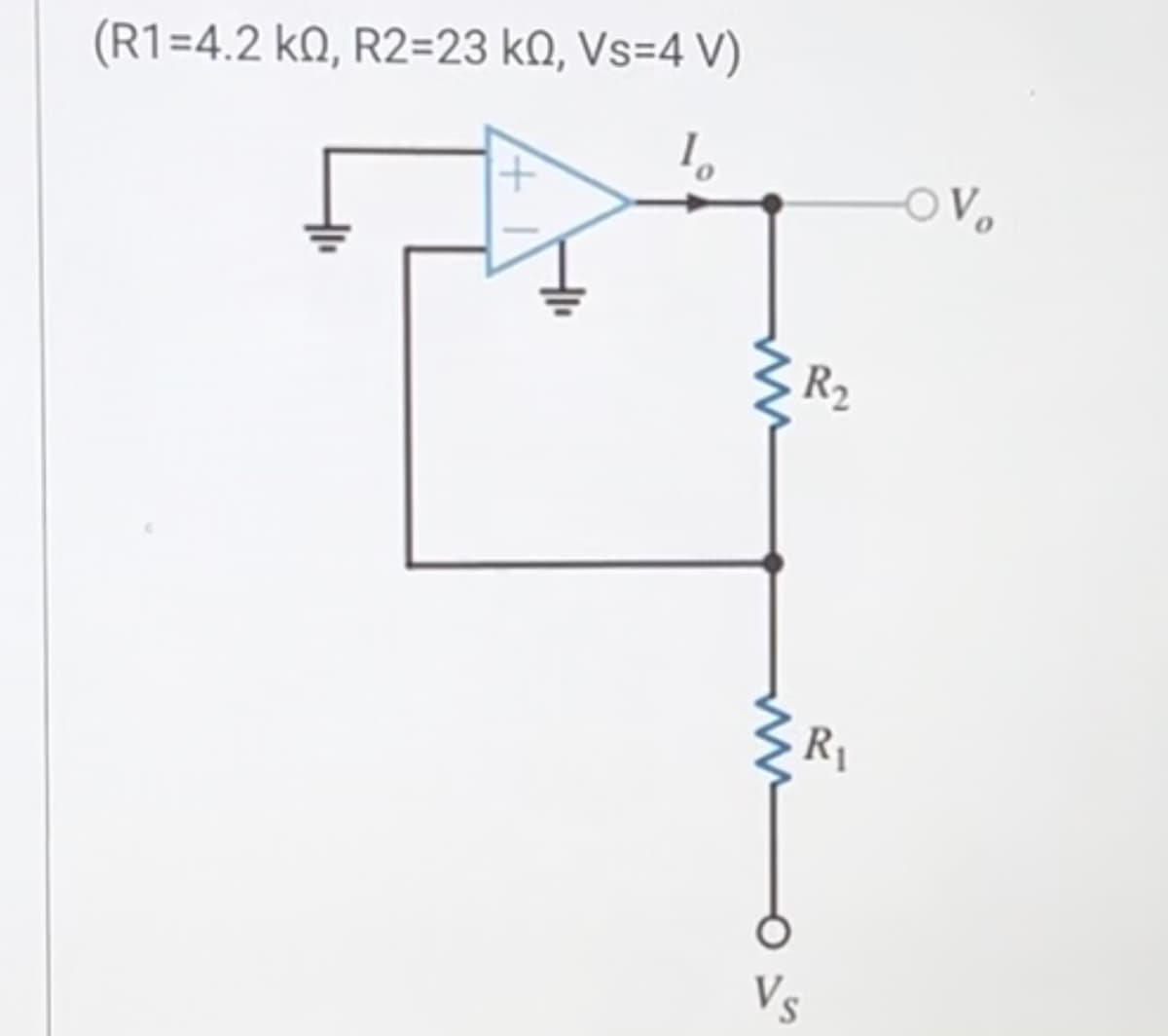
(R1=4.2 k0, R2=23 k0, Vs=4 V) R₂ R₁ -OV


Q: Question 2 You are given an 8:1 mux, the inputs 2-0, and connections to power and ground. Fill in…
A: The given Boolean function needs to be implemented by using the 8x1 mux and the value of the input…
Q: Using a series of source transformations to find io (in A) in the circuit shown below. Show all the…
A: For the given circuit the value of the current io needs to be calculated by using the source…
Q: Vs - is ST₁ T3 Tz T4 + 1
A: The average output voltage of full wave controlled rectifier is, V0 = π(2Vm/π)cosαWhere α is…
Q: For the circuit shown in Figure 2, determine the value for V, and I if the current through the 3 ohm…
A: In this question, we need to determine the value of V if current( I) in 3 ohm resistance is 4A.
Q: 2. Determine voltage transfer function H(o) of this circuit. R₁ R₂ Vin R3 C₁ HE ell Lo -0+ Vout
A:
Q: Using the Voltage Divider rule for the circuit shown below, find: Total Impedance The voltage across…
A: NOTE: As per our guidelines we are supposed to answer first three sub parts of the question. Kindly…
Q: When the average power = 5W, Vm= 10V, Im = 2A, what is the apparent power and the power factor? The…
A: Apparent power= ( S ) VA.Average power= ( P ) watt.Power factor= P/S.RMS value= Maximum…
Q: In terms of Vin, what is the output voltage Vout of the circuit shown? in 2 ΚΩ ww 2 V + 4 ΚΩ ww out
A: The circuit diagram,
Q: PART A PART B 11 (a) 0.5 H inductive load (b) 0.02 F capacitor load (c) 0.05 H inductor load (d) 5 Q…
A:
Q: Dive into the role of the VRM (Voltage Regulator Module) on a motherboard and its impact on CPU…
A: The role of the VRM on a motherboard and its impact on CPU power delivery for overclocking and high…
Q: From the steady space form for this system we can obtained: |--E] The transfer matrix of the system…
A: The question is about multiplication of matrices to finding the transfer function.
Q: Imagine a new kind of flip-flop called a J N flip-flop which has two inputs J and N. Input J behaves…
A: With J and N inputs instead of J and K, a JN flip-flop functions similarly to a JK flip-flop. The…
Q: Find the Laplace Transform of y in the differential equation (D² + 5D + 3)y = 10 Assuming the…
A: Given differential equation Asked to find the Laplace transform of the differential equation?
Q: Example-3 G₁ Gs G₂ H₂ H₂ G6 G using the block diagram representation and the table,find the transfer…
A: Using block diagram reduction method calculation of transfer function:Block diagram reduction method…
Q: 2. Find the fourier transform G(jw) for the function g(t) { where a is a positive constant g(t) =…
A: Question 2 :Given that the signal g(t) is Fourier transform of g(t) is…
Q: The basis for obtaining the output of a Linear Time-Invariant (LTI) system through convolution is:…
A: The basis for obtaining the output of a Linear Time-Invariant (LTI) system through convolution is:
Q: Required information Consider the circuit given below. Vino R₁ R₂ m 12 m 4₁ R3 - Vout Determine the…
A:
Q: Question 2: 201 701 Find the DTFT of x[n] = sin- + cos. Hence, sketch the DTFT for [-41, 3n]. 2
A: Given signal x[n] is DTFT of signal x[n] is and sketch
Q: An RLC series resonance circuit has a resonance frequency of (5000/2π) Hz and impedance at resonance…
A: Here,Resonance frequency, Impedance at resonance, Quality factor,
Q: What are the common applications of microchips in consumer electronics?
A: Microchips, also known as integrated circuits (ICs) or microprocessors, are fundamental components…
Q: Determine the Capacitive Reactance (in Ohms) of a 5 microFarads capacitor for a 60 Hertz frequency.
A: Capacitive reactance (XC) represents the opposition that a capacitor offers to alternating current…
Q: 9. Create a Bode plot of the following transfer function. (1+ jw)(10 + jw)(10k + jw)³ 10(100+ jw)…
A: Given:a transfer function, To do:we need to create the Bode plot.
Q: Solve the following differential equations using Laplace transform; + 2x + x = 21t where x(0) = 1,…
A: Given:Two differential equations:To do:we need to solve above differential equations using laplace…
Q: Y Part A For the circuit shown in (Eigure 1), determine the current through the battery V₁ (positive…
A: The given circuit isR1=10 kΩ.R2=15 kΩ.R3=12 kΩ.R4=19 kΩ.V1=18 V.V2=10 V.V3=24 V.We need to find A.…
Q: Consider the circuit given below. 4.2 ΚΩ www -1 V 6 ΚΩ +1V Μ 2 ΚΩ 7.2 ΚΩ V. 5.4 ΚΩ V₁ Vo If V1 =…
A: The question is about finding the output voltage of Op-amp.
Q: In the ideal transformer circuit shown below, 202 www 240/0⁰ Vrms a) Find 11 and 12 = 1692 www +…
A: The ideal transformer circuit diagram is shown below,
Q: a) Find the value of iL for RL= 2.5 kΩ. b) Find the maximum value for RL for which iL will have the…
A: Given a circuit and asked to find the current and resistance.
Q: 3. Draw 1-V characteristics of 5 V silicon zener diode (Vz-5V) and show its parameters V Vz, Izx,…
A: “Since you have posted multiple questions, we will provide the solution only to the first question…
Q: The following circuit, obtain the Thevenin circuit between terminals a and b
A: For the given circuit the thevenin's equivalent circuit needs to be calculated.
Q: Discuss the impact of power consumption in microchip design and how it relates to the efficiency of…
A: Power consumption is a critical factor in microchip design, and it has a significant impact on the…
Q: The filter described by 1 y[n] = x[n] + x[n 1] is connected in parallel with another filter with…
A:
Q: Use nodal Analysis to find the following. Given V2=26.5 Volt, V3-78 Volt,V4=99 Volt ,V5-92 Volt…
A:
Q: a) Please find v1(0+) b) Please find v2(0-)
A: The given circuit isThe expression of current io(t) is⇒io(t)=50e−8000t[cos(6000t)+2sin(6000t)], mA…
Q: Task 2: The figure shows the frequency response of an element / a system. 1.2 Amplitude ratio 1.1 1…
A: In this question, we need to determine the amplitude ratio of the system at frequency 0.8 rad/s.
Q: Given the following ideal zener diode circuit with breakdown voltage 5.1 V, sketch the output…
A: Given:An ideal zener diode circuit, with breakdown voltage we need to sketch output voltage for…
Q: 2. Find the Z transform of the curve shown in the figure. 3. Using the initial and final value…
A: Given:A signal, To find:z-transform of the given function. Initial and final values of the function…
Q: 03 a. Derive an expression under balanced conditions b. Calculate the Q factor for the coil if the…
A: The given bridge is shown below.We need to derive the expression for balanced condition.
Q: Generate a plot for the skin depth versus frequency for seawater for the range from 1 kHz to 10 GHz…
A:
Q: A unity feedback system has the open loop transfer function shown below. Find the breakin point to…
A: In this question, we need to determine the break-in point of the above system.
Q: The output of the circuit shown is -5 V when the input is 1 V. What is the value of R? What is the…
A: Circuit shown:Feedback resistance is R.
Q: A 2.5-cm long silicon sample has electron and hole densities as 1015/cm³ and 104/cm³, respectively.…
A: Electron VelocityThe drift velocity of electrons () can be found using the equation: where:μe is…
Q: 1) Perform a A-Y conversion on the UPPER delta configuration of Figure 6 and calculate the current I…
A: Given circuit:Asked to perform the to the UPPER delta conversion, then find the current I=?
Q: Problem Assignment 2: The Node Voltage Method 1. For the network below, find IA, IB, and the power…
A: Circuit diagram is given as,
Q: What is a VRM (Voltage Regulator Module), and how does it impact a motherboard's performance?
A: A Voltage Regulator Module (VRM) is a critical component on a computer motherboard responsible for…
Q: Question 1 If you only had 4:16 One Hot Decoder and an OR gate with the number of inputs of your…
A: Here we have to implement a function using a decoder and OR gate
Q: E9.13 Find Vo. 202 50/0° V j4 N 1:2 Ideal 10 Ω www 10 Ω + V₂ -j8n www 6N 4:1 Ideal 0.50 www H -j0.5…
A:
Q: 9. Given the following Boolean Function: F(A, B, C) AB+B(Ā+C) 4 Determine the canonical form for the…
A: Since you have posted multiple questions, we will provide the solution only to the first question as…
Q: Find the h parameters for the circuit in the figure. Take R₁ = 20, R₂ = 15 N, R₂ = 75 N, R4 = 15,…
A: Given network is , R1=20, R2=15 , R3=75, R4=15,R5=75…
Q: 1 Calculate A + B, A- B, A x B and A÷ B for the following pairs of binary numbers. (a) 10110110,…
A: ---->A+BBinary value: 10110110 + 01011011 = 100010001We have to add first number to second…
Q: Consider a induction motor (slip-ring) having a three-phase star-connected rotor. When the stator…
A:

Step by step
Solved in 3 steps with 1 images

- An R-L circuit takes a current 7A that lags behind the 231 V source by 35electrical degrees. Calculate the power factor, impedance, resistance, andinductive reactance of the circuit.A series connection of a 30-ohm resistor and a 100-mH inductor is connected across 240-V, 60-Hz supply. What will be the resulting equation of the current? a. i(t) = 7.04 sin(377t + 51.49°) b. i(t) = 7.04 sin(377t - 51.49°) c. i(t) = 4.98 sin(377t - 51.49°) d. i(t) = 4.98 sin(377t + 51.49°)A series resistance - capacitance ( R-C ) circuit is connected to a 230V, 60 - cycle source. If the power taken by the circuit is 4, 800W and the voltage drop across the resistor is 115V.Calculate the capacitance of the capacitor. 600.36 microfarad 1,500.05 microfarad 556.096 microfarad 250.94 microfarad
- Consider the circuit diagram below. Compute a single equivalent impedance for this circuit for a source frequency of ? =40 Hz. Express your final answer as a phasor with polar coordinates. You must show your all your work for the complex math. Include a diagram of the equivalent circuit as part of your solution.given circuit, Vk = 12 V, R = 240 Ω, C = 1 μF, L = 40 mH. Theswitch, is closed for a long time for t < 0– . Determine vL(t) for t > 0.16. Absolute-value impedance is equal to the square root of:A. G2 + B2.B. R2 + X2.C. Zo.D. Y.
- A resistor of R = 50Ω resistance is in series with a capacitor of C = 150μF. At t= 0, it is suddenly connected to a source of dc voltage of 25V. Determine the current in the circuit at any time t. Determine the current and the voltages across each element at t = 2τ.5.A RL circuit has no applied emf, a resistance of Rohms, an inductance of 2 henries, and an initial current of 10 amperes. Find the current in the circuit at any time t. Use R = 50Equation: Vt= Vm sin 120π t Solve Vrms and Vaverage
- A circuit consists of a capacitor and resistor in series with an AC voltage source, as shown. If VAC max = 24 V, R = 1.2 kΩ, C = 3.0 µF, and the frequency of the AC voltage source is f= 50 Hz, what is the maximum current Imax in the circuit? 32 mA 22 mA 15 mA 11 mA1. The circuit in Figure 1 is in a Continuous Sinusoidal State (SSH). By analyzing the circuit in SSHCalculate the inductance current iL(t) Element values R1=R2=R3=1Ω, e(t)=Cos 3t Volt,It is L=β H. β=4,α=7The equivalent capacitance at terminals a-b in the circuit given is 30 F, then the value of C is Choose correct answer A) 15.98 F B) 0.015 F C) 0.062 F D) 6.2 mF