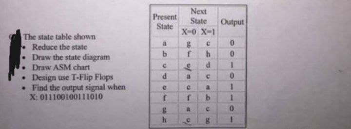
Reduce the state Draw the state diagram Draw ASM chart


Q: Define the term "abstraction."
A: Abstraction: The word “abstraction” means hiding of data. In Java, the term data abstraction is the…
Q: e a state diagram with entry, do and exit activities.
A: Here begin is entry symbol and any activity is started with that symbol only . ___ Do is condition…
Q: 1. Diagram 1 is a value 8 counter, please draw the schematic by design software, take the schematic…
A: Compared with the single tone, I used p_nTone control as a RF source and the following settings…
Q: Draw the schematic Diagram of F= Ā B Z + ABE
A: We are given a boolean expression and we are going to find out its schematic diagram using gates.…
Q: Control System: Apply the 7 rules of Block Diagram and Show your COMPLETE solution in a step by step…
A: Rule 1: Blocks In Series/Cascade Blocks in series are multiplied to get output block. If 2 blocks G1…
Q: Answer the following questions: 1. For the following Boolean expressions, simplify if simplification…
A:
Q: Fingerprint voting system Class diagram
A: the diagram is an given below:
Q: Compare a state machine diagram with a sequence diagram and discuss the differences between the two
A: What is State Diagram? A state diagram (also called state machine diagram, statechart and start…
Q: Draw block diagram of F.A using two H.A. ( H.A+H.A=F.A)
A: Given: Draw block diagram of F.A using two H.A. ( H.A+H.A=F.A)
Q: 8.Examine the following and describe each part in detail along with their effects and…
A: In this question we have given some attributes of a HTML tag and we need to explain effects and…
Q: O Draw the Symbol of EXOR gate. (ii) Draw Ladder diagram of EXOR. (v) Write the name of the symbols…
A: The answer is given in step 2.
Q: Draw the block diagram of the functional units of a computer system
A: A computer system is a set of Integrated device that input, output, process and store data and…
Q: Q1) Draw Digital IC Design Flow Diagram, and clarify the difference between pre-layout and…
A: Answer :
Q: draw a hierarchy chart and design the logic for a program for Arnie's Appliances. Design…
A:
Q: a. Explain and discuss the steps of CAD flow design. Relate each step to the part you have done in…
A: a) explain and discuss the steps of CAD flow design. Relate each step to the part you have done in…
Q: Identify the problems in the below given diagrams. You will get extra marks for identifying…
A: Please give positive ratings for my efforts. Thanks. ANSWER Below are the problems present on…
Q: 4- Design views are: a. Top, bottom, and side views of the IC b. More expensive than designs without…
A: Ans 4: Design views are : c) different description of the design Ans 5: Design hierarchy is: d) A…
Q: Draw state stable and diagram for below diagram.
A:
Q: Define each of the following PLD programming terms:(a) design entry (b) simulation (c) compilation…
A: Answer: (a) Design entry The first step in the programming process enables the programmer to enter…
Q: Name five typical symbols used on block diagrams.
A: “Since you have asked multiple question, we will solve the first question for you. If you want any…
Q: 2. Draw a logic diagram and create a truth table for a'b'd + a(a+b') + acd' 3. Draw a logic diagram…
A: Truth Table of a'b'd + a(a+b') + acd' : Let F= a'b'd + a(a+b') + acd' Logic Diagram of a'b'd +…
Q: Given the truth table below, provide the output equations and Diagram
A:
Q: z = Axy + Bx'y raw the logic diagram. erive the state table. erive the state diagram.
A: Here depending upon input of flip flop, we need to draw the state table first. Then from state…
Q: true /false 1) The use case diagram expresses how a system performs. ( )
A: It is a pictorial illustration of actors of the system and their interactions with the system. It…
Q: crowsfoot diagram
A: ANSWER: Crows Foot: Crows foot diagrams address elements as boxes, and connections as lines between…
Q: /false A state chart
A: Lets see the solution.
Q: An electric ceiling fan has a pull rope as a switch. From off position when the rope is pulled, the…
A: As per our guidelines, only 3 sub parts will be answered. Kindly repost other sub parts separately.…
Q: Can you elaborate on the Ring algorithm
A: The Ring Algorithm — This algorithm is for ring-organized systems (logically or physically). We…
Q: As stated before, transitions and triggers may be found in state diagramming. 3.1 Show the various…
A: When a specific event happens and stated criteria are met, a transition is a relationship between…
Q: Define Action Center
A: Define Action Center -> The Action Center : The Action Center is a utility in modern…
Q: In Verilog Code, Please and thank you!
A: The comparator's corresponding equations: A_greater_B = B0 B1 A0 + B1 A1 + A1 A0 B0…
Q: Please tell me if you have any examples of discrete event simulation.
A: Answer: Here is the example of discrete event simulation. For example, a truck shows up at a…
Q: I know the answer with almost all steps. I'm only asking some. How is the transition from time…
A: D-type Flip Flop The D flip-flop is an edge triggered device which transfers input data to Q on…
Q: convert the communication diagram into a sequence diagram
A: Below we convert the given communication diagram to sequence diagram:…
Q: A coupling diagram shows: Select one: a. Where the variables are located in the modules. b. The test…
A: Given:
Q: Complete the diagram
A: Here we will complete the diagram
Q: Design UML diagram of car rental system
A: Given: Design UML diagram of car rental system
Q: For the system of an air condition draw the following three using Microsoft Visio: The…
A: Air conditioner block diagram:
Q: what is the figure doing in this diagram. Please explain figure 5-20. the answer come from the other…
A: as given in questions we have to explain the design of accumulator and controlling of accumulator…
Q: Write the Boolean algebra expressions and simplify using Karnaugh map for the following table of…
A: Solution: Here I am using KMAP to simplify the given table: X = A'B + AB' + AC Y = A'B' + BC
Q: What are the considerations for designing a system interface pertaining to information onset display
A: System Interface: Two or more components of a computer system exchange information through a shared…
Q: draw a use case diagram about COVID-19 Vaccination System.
A: Use case diagrams describe the high level functions and scope of a system. These diagrams also…
Q: The state diagram illustrates the same information listed in: a. Truth table b. none of the options…
A: Given: The state diagram illustrates the same information listed in:
Q: Define a CFG and PDA for the language. Write down a CFG and a diagram for PDA L = {w | w ∈ {a,b}* ∧…
A: Offer an overview of pivot: Turning or spinning around the center point is known as pivoting.…
Q: Make 5 questions about this diagram
A: the five question on the diagram is an given below :
Q: Draw a DFA’s Transition Diagram and Transition Table that would accept string: a2b2aba can i please…
A:
Q: 3) Describe the machine cycle. Give a sample scenario.
A: The question has been answered in step2

Step by step
Solved in 2 steps with 3 images


- Draw a state diagram and truth table for the following problem: Design a sequential circuit. For every three bits that are observed on the input w during three consecutive clock cycles, the machine generates a bit z=1 if and only if the number of 1s (ones) in the three-but sequence is 2 (two); otherwise z=0.Sequence RequirementThe following are the sequence requirement for this project.• At first state (00) and third state (10): The system transitions to the next state when the long timer goes OFF.• At second state (01) and fourth state (11): The system transitions to the next state when the short timer goes OFF.Therefore, add the sequence requirement into state diagram from Lab 2, your new state diagram is shown in Figure 2.PART 1: DESIGN1.1 Design a 2-bit binary counter using D flip-flops. Consider the long timer, TL and short timer, TS as your control inputs for the counter to work. As shown in Figure 1, the output from this counter, will be inputted to the combinational logic circuit. Show all your design steps (truth table, equation, and circuit implementation).2a.Name three drawbacks of a digital system over an analog systems 2b. If a computer runs at 12.8 GHz, what is the period of its clock signal?
- If there is no forwarding, what new inputs and output signals do we need for the hazard detection unit in Figure 4.60? Using this instruction sequence as an example, explain why each signal is needed.Assume we have a 16-bit Arithmetic Logic Unit (ALU) that has three inputs and three outputs. List the inputs and outputs in binary for the ALU if we are using it to determine if X = 2510 < Y = 3210. The ALU. Use 16 bits or 1 bit to represent the inputs and outputs as appropriate. The value for ALU operation will be (11)2 for Set on Less Than.Consider a 32-bit machine where four-level paging scheme is used. If the hit ratio to TLB is 98%, and it takes 20 nanosecond to search the TLB and 100 nanoseconds to access the main memory what is effective memory access time in nanoseconds?
- 31. The factors that define QoS are : a. Throughput b. Jitter c. Delay d. All of the mentionedQ#02) Explain Direct Memory Access (DMA), and Input/output timing diagram with clock synchronization.Moore state diagram (output inside the state and input on the transition arrow) Two bit binary for the coin output and coin input and 1 bit for soda Input and output binary encodings $0 = “01” 50cent = “10” $1 = “11” $0 = “00” Make a state table From the attached state diagram(moore machine) Inside the states the the two outputs shown and seperated by “/“ are in the order of change (2bit binary) and soda(1bit binary)
- Draw the control unit and datapath for the following algorithm that returns an integer value. The function takes two points (x1, y1) and (x2, y2) and computes the equation for a line. It then evaluates and returns ynew for the parameter xp using that line. Use a 16-bit data bus. Show your work; label and clearly mark your diagram. Do not implement this in VHDL. int PredY(int x1, int y1, int x2, int y2, int xp) { int m, b, ynew; if (x1 – x2) <> 0 { m = (y1 - y2) / (x1 - x2); b = y1 - m * x1; ynew = m * xp + b; return(ynew); } else { return(65535); // that's a 16-bit FFFF } }8.- Consider that the serial velocity is given by: baud_rate=Fosc/k(n+1) It is required to communicate at 1200 bps with a 1MHz clock and K=16 n=5. What is the real speed generated with the value stored in the SPBR6 register?ASSEMBLY What is the result of executing: mov bx, 0ABCDh shr bx, 1 55E6 6E55 E635 33E7