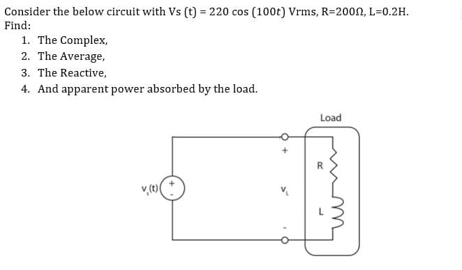
sider the below circuit with Vs (t) = 220 cos (100t) Vrms, R=2000, L=0.2H. d: 1. The Complex, 2. The Average, 3. The Reactive, 4. And apparent power absorbed by the load. Load v(t) R


Q: 3-A 400 kV, 50 Hz, 700 km long symmetrical line is operated at the rated voltage. a) Calculate the…
A: “Since you have posted a question with multiple sub-parts, we will solve the first three sub-parts…
Q: * For the following circuit if the secondary voltage of the transformer is 20V max, the output…
A: We need to select correct option for output voltage for given circuit
Q: Indicate graphically the effect of increasing the source resistor RS on the Q-point of the JFET. Va…
A: JFET(Junction Field Effect Transistor): One of the most basic varieties of field-effect transistor…
Q: Chapter 17: Problem 4 (Series-Parallel): For the network shown below, find: a) The total impedance…
A: As per the guidelines of Bartley we supposed to answer first three subpart only
Q: h3(n) = (2√2)" sin (n) u(n) 3 2.1 Determine the system function H(z). Simplify your answer to one…
A: A system diagram represents the visual model of a system its components and its behaviors.
Q: + VR www R = 100 E 12 V Xc a) Find the value of X₁ for resonance. b) Find the quality factor Q c) If…
A:
Q: For The block diagram shown below, the plant is given by G(s)=- k G stable for any value of K never…
A: We need to find out the range of k for which the given system is stable
Q: For the cascaded system shown below determine the output voltage if vs = 1mV. Avi Av₂…
A:
Q: system produced, 3 poles in the left-half plane, 4 in the jw-axis and 0 in the right-half plane. The…
A: We need to select correct option for given system
Q: B) You have a choice between a cable where the transformer box is at the very end (right where you…
A: The loss in a cable is given by I2R where I is the current and R is the resistance of the cable.…
Q: design 3 phase diode rectifier
A: The objective is to determine the design of three phase diode rectifier.
Q: Please find Fourier Series coefficient for the figure given below. -3/2 -5/2 4/2 -V2 5/2 Your…
A: Calculation of Fourier series coefficient of given figure below : We know,Fourier series…
Q: Solve the base current (IB) of Figure 611. VCC 8.92 UA 2.56 UA 10.74 UA 1.07 uA R1 680k 18V R2…
A: Consider the given diagram for the npn transistor. The input resistance is of 680 kohm. The Vcc is…
Q: If Vz-8 V and Pzmax=150mW. Determine the minimum value of RL to ensure the * Zener diode is in the…
A:
Q: Solve for Ic of Figure 41. VCC T15V O 0.33mA O 4.77mA O 3.3mA O 0.477mA R1 $390KQ R2 $2.7kQ2 Q1 Beta…
A: Bipolar Junction transistor (BJT):- It is a three terminal device that is Emitter, base and…
Q: 1 - Regarding flip-flops, it can be said that: Choose an option: A. when the inputs of a JK…
A: Flip-Flop :- It is electronic circuit that has two stable state to store the binary data and…
Q: For the F(x) function shown in the figure, find P(0≤x≤0.5) F(x) 1 1 2 O 0.4999 0.5000 O 0.5999 O…
A:
Q: Four wires of same material, the same cross-sectional area and the same length when connected in…
A: Given, Four wires are connected in parallel having, Same material, same length and same cross…
Q: 10. A linear system has the transfer function given by W H(w) = w² + 15w+5 Find the power spectral…
A: We need to find out psd of output
Q: Laplace Transform of the following functions
A: In this question we will find laplace transform of given signal....
Q: By using thevenins theorem for the circuit shown in Figure below, to find the current in the 3 ohm…
A:
Q: What is the input to the system with specification given, Kp = 10, 500? A. Step function B. Ramp…
A: Answer:A step function.
Q: + 4₁ = 10 μA 18 mV 0.6 k BJT transistor amplifier AUNL V=3.6V Activate Windr
A: BJT is a bipolar junction transistor transistor it have three terminal first one is base, second is…
Q: + VR www R = 20 + VL moo XL = 30 Ω + E50 mV Xc a) Find the value of X, for resonance. And find the…
A: In this solution we discuss about the series resonance.
Q: Q2/ In Radial Distribution System (11kv) as shown in fig and table: FIND 1-Voltage drop of each…
A: As per Bartleby policy we can answer first three sub parts only. Please repost the question for…
Q: If Vz=8 V and Pzmax=150mW. Determine the minimum value of RL to ensure the Zener diode is in the ON…
A: We need to find out the value of load resistance
Q: A circuit that controls a given digital system has three inputs: x1, x2 and x3. It has to recognize…
A: Given data : X1,X2,X3 are digital input , Condition A is true only when X3 is true and (X4 is true…
Q: The number of bits required for a binary code to represent 712 different possibilities is Select…
A: Given data, Total required possibilities are 712.
Q: Consider the following system diagram x(n) h₁(n) h₂(n) Given the following h1(n)= {2,2,1} ↑ (-) u(n)…
A: The given system diagram is shown below, Where,h1[n]=2↑, 2, 1h2[n]=12nu[n]h3[n]=223nsinπ4nu[n]
Q: Problem 19: For the RC Low-Pass filter shown below, sketch the filter's magnitude response and phase…
A: RC low pass filter: This filter passes the signals below the cut off frequency (fC) and after that…
Q: (4) A particular signal has a waveform given by Find the power spectrum of this signal. V(t) =…
A: We need to find out power spectrum of given signal
Q: What is the impulse response of a stable discrete-time system with the following mathematical…
A:
Q: Using the following characteristics, determine Bac at IB = 60 uA and VCe= 5V t/c (mA) (HA) V=IV VCE…
A: We need to select correct option for beeta for given characteristic
Q: Given circuit represent the logic for which gate? A B Select one: a. None b. NOR c. OR d. NAND e.…
A: Given logic circuit:
Q: The overall transfer function for the system below is
A:
Q: For the root locus shown below, the break in point is -25 -20 -15 -10 03 O-18 -10+9i -10
A: Given: Root locus
Q: % contribution = R31 R3E1+1R3E2+1 R31 R₁ 5 Ω + x 100 R₁ R2 402 E₁ R3 5Ω a R4 8 Ω R₂ C E₁ 11 V b E2 8…
A: Given circuit shown R1=5 ΩR2=4 ΩR3=5 ΩR4=8 ΩE1=11 vE2=8 vI=3 A
Q: following Consider FET is idea
A: NOTE- “Since you have posted a question with multiple sub-parts, we will solve first three subparts…
Q: Solve for VE of Figure 43. VCC T21V V₁ R1 3500ΚΩ R2 $2.1kQ Q1 Beta = 110 R3 {1.2ΚΩ Figure 43 Vc VE
A:
Q: For the cascaded system shown below determine the total voltage gain. A Av₂ Emitter follower…
A:
Q: R₁ ≤652 RI www R₂=452 Ru= 352 8v ww R3= 2√2
A:
Q: given the circuit below, compute for the following a. Source phase voltages b. Source line voltages…
A: In this question, We need to determine the source phase voltage, source line voltages and line…
Q: Explain the effects of power factor on motor effects
A: The power factor of the induction motor is determined by its material of construction. Materials of…
Q: * Photo diodes can be used in the industry to Used as a light O Count the number of emoloyees O…
A: 1) - Photo diode is electrical component which produces electrical current when light is incident on…
Q: Problem 14: Find the currents I₁, I₂ in phasor form. I= 20 A 240° 000 40 I=6A430° R2201 600 R 1₂ (a)…
A:
Q: Which one is the most efficient electrical device? a) LED light b) Incandescent light c) Subwoofer…
A: Nowadays more energy efficient electrical devices are used to decrease the burden on power systems…
Q: er ways for obtaining a D latch. In each case, ify the circuit operation. En D Next state of Q
A: Solution- (a) Table- En D Next state of Q0 x No change1 0 0; Reset…
Q: The DC armature resistance between the terminals of a 750kVA, 4,400-volt, Y-connected, 3phase…
A:
Q: The reversible steady flow process 1-2-3-4-5-3 o
A:
Q: What is the noise power for a band with of 13.5 kHz at 20°C? Determine the noise power density when…
A:

Step by step
Solved in 3 steps with 3 images


- A ower system is operating at 1000Mw, 132kV, 50Hz, with 0.8 p.f. laging in parallelwith another line at 750OMW, 132kV, 50Hz with 0.707 p.f. lagging. Both are interconnectedat the station and when the compensating device is on, the overall power factor isimproved to 0.9 lagging. Suggest suitable capacitors, shunt and series. Individual loadsand combined load are to improve power factor to 0.9 in all cases.A Δ-connected, 60−Hz, balanced, 3ϕ, positive-sequence voltage source is connected to a Δ-connected, symmetric 3ϕ load via a non-ideal transmission line. The line-line voltage magnitude of the source is 480VRMS. The series impedance of each phase of the transmission line is 0.1+j1.5Ω. The impedance of each leg of the load is 3+j6Ω. a. What is the total, 3ϕ complex power consumed by the load. b. What are the total active power losses (all three phases) in the transmission line?A 34.5 kV station has a short circuit impedance of at givenpoint of 0.21 pu based on 100 MVA. Determine theinterrupting capacity of the circuit breaker needed.
- A 550-V feeder line supplies an industrial plant consisting of a motor drawing 60 kW at 0.75 pf (inductive), a capacitor with a rating of 20 kVAR, and lighting drawing 10 kW. (a) Calculate the total reactive power and apparent power absorbed by the plant. (b) Determine the overall pf. (c) Find the current in the feeder line.The sending-end voltage in the circuit seen is adjusted so that the load voltage is always 13,800 V(rms). The variable capacitor is adjusted until the average power dissipated in the line resistance is minimum. 1. a) If the frequency of the sinusoidal source is 60 Hz, what is thevalue of the capacitance in microfarads?2. b) If the capacitor is removed from the circuit, what percentageincrease in the magnitude of Vs is necessary to maintain 13,800V(rms) at the load?3. c) If the capacitor is removed from the circuit, what is thepercentage increase in line loss?An industrial load of200KW has a powerfactor of 0.5 lagging. Agroup of synchronousmotors operating at apower factor of 0.8leading is installed andthe over-all power factorimproves to 0.75 lagging.Determine the KVArating of the synchronousmotors installed.Answer = 130.2354 KVA
- Circuit elements with an inductance of 200 mH, a capacity of 50 μF and a resistance of 10 Ω are connected in parallel. If the average value of 198 V sinusoidal AC voltage is applied to this system, find the line current, impedance and phase angle of the circuit. (Take the frequency as 60 Hz.)A 3 phase 170KV, 50 HZ transmission system is 170km long. The resistance is 0.5Ω/km/phase, inductance of 1mH/km/phase and capacitance of 2nano farad/km/phase. The line delivers 60MW and 93MVAR at 170KV line to line voltage. Using suitable mode determine sending and receiving end currents. What can you infer from the result?Two buses are interconnected by a transmission line of impedance (0.03 + j0.012) pu. The voltage on one bus is 1/0°, and the load on the other bus is (1 + j0.4) pu. Determine the voltage on the second bus. Also calculate the real and reactive power on the first bus.
- 2. Solve the following problem: A THREE-PHASE PLANT CONSUMES 600 KVA, WITH A VOLTAGE OF 2400 VOLTS AND A POWER FACTOR OF 0.8 BEHIND. a) DETERMINE THE EQUIVALENT DELTA IMPEDANCE OF THE PLANT. b) IF THE PLANT WERE A STAR, CALCULATE THE RESISTANCE, REACTANCE AND THE CORRESPONDING PASSIVE ELEMENT.A transmission line of impedance (0.05 + j0.02) pu interconnects the buses of a switchyard and a bulk supply point. The receiving end apparent power is (1.0 + j0.6) pu and sending end voltage, 1/0°pu. Estimate the following: i) Receiving end voltage after two iterations ii) Perform two further iterations to test the convergence of the value of receiving end voltage deduced in (i) iii) load currentThe sample large power system network data's are given below, The total number of buses is 5 Three-phase short circuit fault subjected at the bus 5 The initial voltage of the faulted bus is 1.0 p.u The Zbus matrix element Z55 is 0.774 p.u Fault impedance Zf= 0.39 p.u