Since k = 0.35x10⁻³, VGSQ = 6.2 V, VGS(Th) = 2.4 V, RF = 100 MΩ, RG = 10 MΩ, RD = 7.6 kΩ, RS = 2.2 kΩ and RL = 8.7 kΩ in the circuit in the figure In which option is the amplitude value (Vout) of the output voltage given correctly? NOTE-1: E-MOSFET output impedance is rd = 70 kΩ and should be taken into account in calculations. NOTE-2: Capacitors are of negligible size at mid-band frequency. NOTE-3: It is within the 5 kHz mid-band frequency. Since k = 0.35x10⁻³, VGSQ = 6.2 V, VGS(Th) = 2.4 V, RF = 100 MΩ, RG = 10 MΩ, RD = 7.6 kΩ, RS = 2.2 kΩ and RL = 8.7 kΩ in the circuit in the figure In which option is the amplitude value (Vout) of the


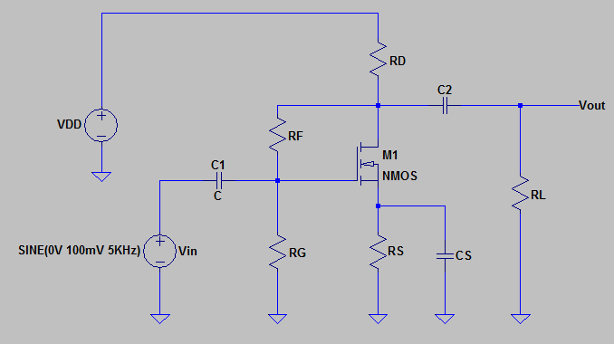
Since k = 0.35x10⁻³, VGSQ = 6.2 V, VGS(Th) = 2.4 V, RF = 100 MΩ, RG = 10 MΩ, RD = 7.6 kΩ, RS = 2.2 kΩ and RL = 8.7 kΩ in the circuit in the figure In which option is the amplitude value (Vout) of the output voltage given correctly?
NOTE-1: E-MOSFET output impedance is rd = 70 kΩ and should be taken into account in calculations.
NOTE-2: Capacitors are of negligible size at mid-band frequency.
NOTE-3: It is within the 5 kHz mid-band frequency.

Step by step
Solved in 2 steps with 2 images


