Solve equation V1 = 30V V2 = 60v V3 = 60V 12 ar 3 Am tsolve lit using System of Katar eq
Solve equation V1 = 30V V2 = 60v V3 = 60V 12 ar 3 Am tsolve lit using System of Katar eq

Power System Analysis and Design (MindTap Course List)
6th Edition
ISBN:9781305632134
Author:J. Duncan Glover, Thomas Overbye, Mulukutla S. Sarma
Publisher:J. Duncan Glover, Thomas Overbye, Mulukutla S. Sarma
Chapter6: Power Flows
Section: Chapter Questions
Problem 6.61P

Related questions
Question
3) solve the circle using Using System of linear equation
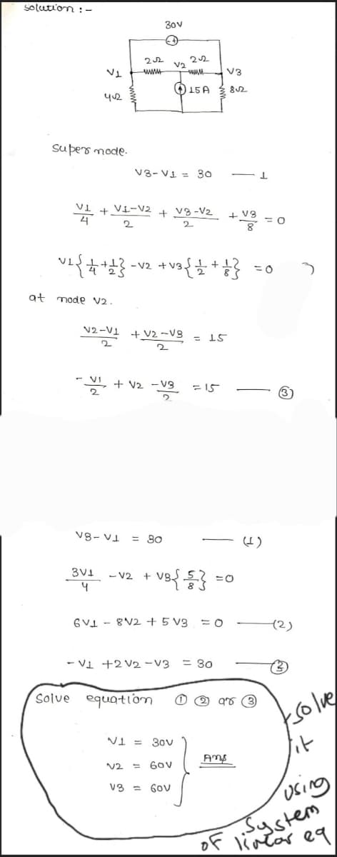
Transcribed Image Text:solution :-
at
V1
412
super mode.
~2 { + +1}
mode V2.
22
www
V8-
VI
V1 + VI-V2 + V8-V₂
2
2
30v
(+
2-1 + 2-3
2
-V2 + V3
VI+V2 -V3
V₂
V3-V1 = 30
= 80
3V1 -V2 +
4
V2
22
Solve equation
www
15 A
V1 = 30v
60v
V3 = 60v
+
-VB{{}}
6V8V2 + 5 V3 = 0
15
= 15
- V1 +2 V2 -V3 = 30
V3
8√2
Amp
IF
+ V3
98
= 0
=0
(2)
(3)
tsolve
lit
using
System
of linear eq
Expert Solution
This question has been solved!
Explore an expertly crafted, step-by-step solution for a thorough understanding of key concepts.

Step by step
Solved in 2 steps with 2 images

Knowledge Booster


Learn more about
Need a deep-dive on the concept behind this application? Look no further. Learn more about this topic, electrical-engineering and related others by exploring similar questions and additional content below.Recommended textbooks for you
Power System Analysis and Design (MindTap Course …
Electrical Engineering
ISBN:
9781305632134
Author:
J. Duncan Glover, Thomas Overbye, Mulukutla S. Sarma
Publisher:
Cengage Learning
Power System Analysis and Design (MindTap Course …
Electrical Engineering
ISBN:
9781305632134
Author:
J. Duncan Glover, Thomas Overbye, Mulukutla S. Sarma
Publisher:
Cengage Learning