Solve for: 1. Current Al: uA 2. Voltage Vout: V 3. Gain =

Delmar's Standard Textbook Of Electricity
7th Edition
ISBN:9781337900348
Author:Stephen L. Herman
Publisher:Stephen L. Herman
Chapter18: Resistive-inductive Parallel Circuits
Section: Chapter Questions
Problem 13PP: In an R-L parallel circuit, IT=1.25 amps, R=1.2k, and XL=1k. Find IR

Related questions
Question
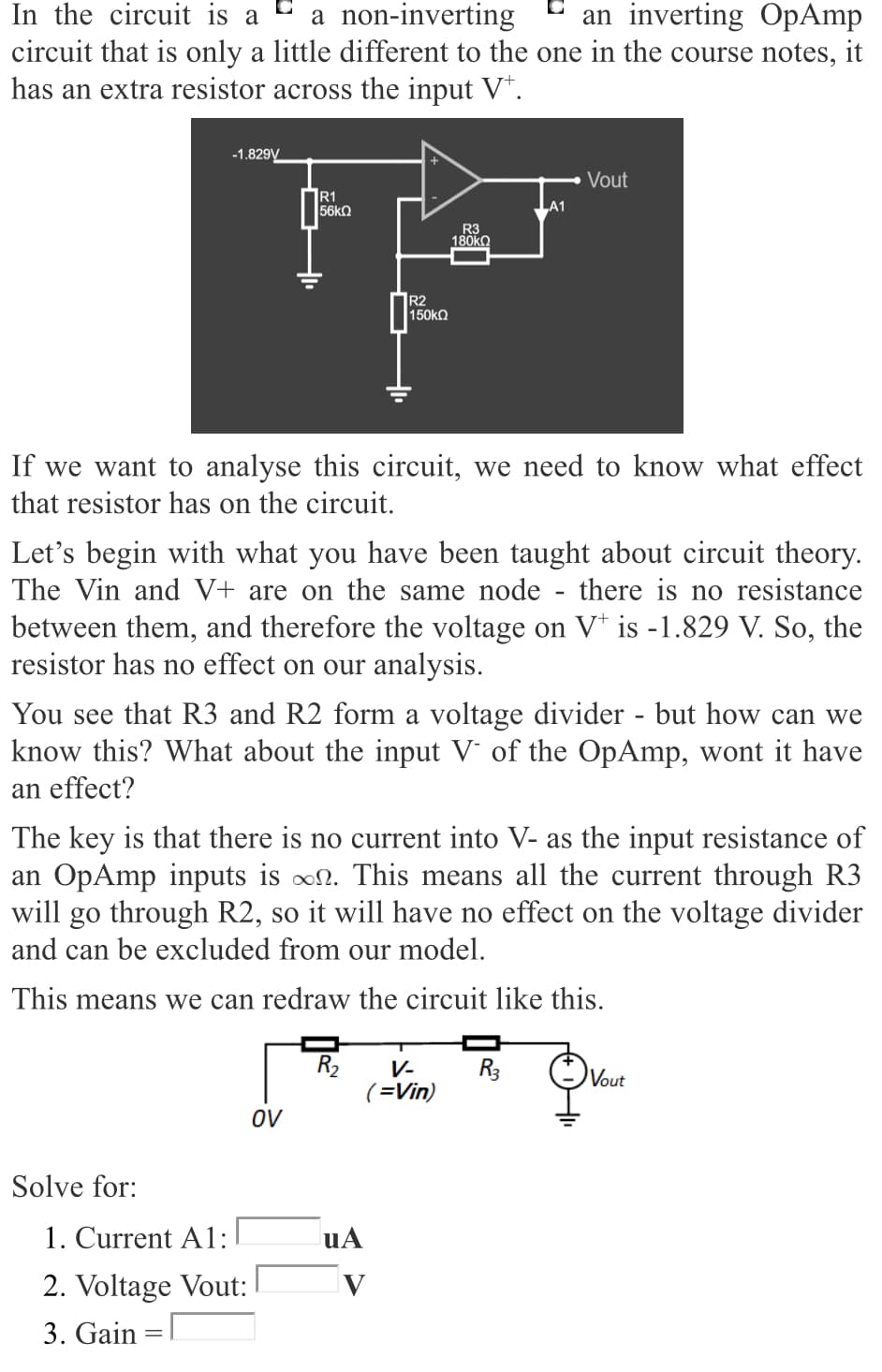
Transcribed Image Text:In the circuit is a
circuit that is only a little different to the one in the course notes, it
has an extra resistor across the input V*.
a non-inverting
an inverting OpAmp
-1.829V
Vout
R1
56k2
R3
180KO
R2
150kO
If we want to analyse this circuit, we need to know what effect
that resistor has on the circuit.
Let's begin with what you have been taught about circuit theory.
The Vin and V+ are on the same node
there is no resistance
between them, and therefore the voltage on V* is -1.829 V. So, the
resistor has no effect on our analysis.
You see that R3 and R2 form a voltage divider - but how can we
know this? What about the input V' of the OpAmp, wont it have
an effect?
The key is that there is no current into V- as the input resistance of
an OpAmp inputs is on. This means all the current through R3
will go through R2, so it will have no effect on the voltage divider
and can be excluded from our model.
This means we can redraw the circuit like this.
R2
V-
R3
Vout
(=Vin)
OV
Solve for:
1. Current A1:
uA
2. Voltage Vout:
3. Gain =|
Expert Solution
This question has been solved!
Explore an expertly crafted, step-by-step solution for a thorough understanding of key concepts.

Step by step
Solved in 2 steps with 2 images

Knowledge Booster


Learn more about
Need a deep-dive on the concept behind this application? Look no further. Learn more about this topic, electrical-engineering and related others by exploring similar questions and additional content below.Recommended textbooks for you
Delmar's Standard Textbook Of Electricity
Electrical Engineering
ISBN:
9781337900348
Author:
Stephen L. Herman
Publisher:
Cengage Learning
Delmar's Standard Textbook Of Electricity
Electrical Engineering
ISBN:
9781337900348
Author:
Stephen L. Herman
Publisher:
Cengage Learning