specifying values at all change of loading


Q: Assignment Problem 12.1. Calculate and draw the shear and moment diagrams for the beam and loading…
A:
Q: a) Develop the shear force and bending moment equations for each section. b) Sketch the shear force…
A: Calculate the reaction at A and B
Q: Compute the shear and moment values and draw the shear and moment diagrams of the beams loaded as…
A:
Q: Draw shear and moment diagram then determine the maximum shear and maximum moment. Use 3 decimal…
A: Given Simply supported beam and it is asked To draw the shear force and bending moment diagram
Q: Draw the shear and bending moment diagrams for each beam loaded as shown 1. 150 k-ft 60 k B C -10…
A:
Q: PART 2: For the given Statically Determinate Beams, Perform the following. Write the Shear and…
A:
Q: Without writing the shear and moment equations, draw the shear and moment diagrams of the beams…
A: Shear Force Diagram (SFD) :
Q: Beam 3 A P Tund L/4- W -3L/4- B
A:
Q: Problem 12.1. Calculate and draw the shear and moment diagrams for the beam and loading shown in the…
A: calculate support raections∑Fx=0; VA+VC=1+3=4point B is subjected to internal hinge So Bending…
Q: Draw the shear and moment diagrams for the beam
A:
Q: Write the shear and moment equations for the beams loaded as shown and sketch the shear and moment…
A:
Q: diagrams method of equations. Locate and detemine the zero shear moments and all the necessary…
A:
Q: Write the shear and moment equations for the beams in the following problems. Then draw the shear…
A: We will draw shear and bending moment diagram
Q: y Wo
A:
Q: ACTIVITIES: Compute the shear and moment values and draw the shear and moment diagrams of the beams…
A:
Q: The Built Up Beam shown is made by connecting two channel shapes and two plates, using 0.75"…
A: Draw the schematic diagram for the beam as follows:
Q: Q2/ Use the graphical method to construct the shear-force and bendir for the beam shown. Label all…
A:
Q: determine the shear and moment of the following beams. draw the shear and moment diagram and…
A: Answer We are given a free body diagram of a overhanging beam. Since the beam is symmetrically…
Q: Write the shear and moment equations
A:
Q: 2. Draw the shear and moment diagrams for the beams loaded as shown without writing the shear and…
A: From the given question it is required to calculate the shear force and Bending moment for each…
Q: Question 8 Draw the shear and moment diagrams for the beam loaded at its center by the couple C.…
A: If any body is in in equilibrium then : Sum of all the forces in x-direction must be equal to zero…
Q: 30 kN A 1m B 3 m 50 kN C 2 m D
A: The length of beam, L=6mThe loads are 30KN, 50KN
Q: Use the graphical method to construct the shear-force and bending-moment diagrams for the beam…
A: Given data: Simply supported beam with UDL and moment L= 11.5 m, w = 22 kN/m, MA = 86 kN-m, MB =…
Q: d to construct the shear-force and bending-moment diagrams for the beam shown. Let a = 3.9 m, b =…
A:
Q: MA = 12 kN. m w = 3 kN/m 6 m-
A:
Q: 20 kN 2 m 2 m 2 m 40 kN/m 20 kN/m
A: Σ Fx = 0 Σ Fy = 0 R1 + R2 = 20 + 20×4 + 40×2 R1 + R2 = 20 + 80 + 80 R1 + R2 = 180 KN Taking moment @…
Q: 5 kN/m В 70KN 70KN 3 m- 5 m 3 m
A: Draw the free body diagram. Equilibrium of horizontal forces, ∑Fx=0Ax=0
Q: Q2\ Draw Axial, shear and bending moment diagram for the beam shown below. • The details for the…
A:
Q: Draw the Shear and Moment Diagram for the given loadings below using Method of Section and Method of…
A:
Q: Compute the shear and moment values and draw the shear and moment diagrams of the beams loaded as…
A: Solution Given Diagram
Q: Write the shear and moment equations for the beam loaded as shown, then sketch the shear and moment…
A: Answer: Let us first calculate the reactions at B and C Consider Vertical equilibrium RB + RC = 12*…
Q: 10KN/m 90kN/m 30 kN/m A 2 m 2 m 3 m R2 R1
A: NOTE - We’ll answer the first question since the exact one wasn’t specified. Please submit a new…
Q: 2 1000 LB 21 R 4 FOR THE BEAMS SHOWN. WRITE THE SHEAR AND MOMENT EQUATIONS AND DRAW THE V- AND M-…
A:
Q: Draw the shear and moment diagram, and the elastic curve of the loaded frame shown. Show complete…
A: Question is based on the frame subjected to uniform load . Length of span and magnitude of load are…
Q: SHEAR AND MOMENT DIAGRAM PROBLEM 2 Use the AREA method to construct the shear-force and…
A:
Q: 200 lb/ft A C D Hinge B - 2 ft →e- 4 ft - 2 ft
A:
Q: Use the graphical method to construct the shear-force and bending-moment diagrams for the beam…
A:
Q: F2 RI Find the shear and moment diagram of this beam. Use graphical method and show how each area is…
A: Solution:-1. Shear force at various sections:
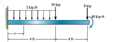
Q: 10 kip 8 kip 3 kip/ft 40 kip-ft
A: Solution:
Q: 3 kips/ft | 4 kips B C В D A -3 ft - 4.5 ft– 1.5 ft
A:
Q: 12 AN/m 40 IN
A: Draw FBD:
Q: Use the graphical method to construct the shear-force and bending-moment diagrams for the beam…
A:
Q: For the beam shown, you must draw, applying the method of sections, the shear and moment diagrams.…
A:
Q: Use the graphical method to construct the shear-force and bending-moment diagrams for the beam…
A: Given data : a=7.5 m b=2.5 m w=27 KN/m P=44 KN MB=67 KN×m
Q: Determine the functions for internal shear (V) and moment (M) as functions of x (measured from the…
A:
Q: 3 kips/ft | 4 kips B C D A – 4.5 ft 3 ft→ 1.5 ft
A: The bending moment is equal to the vertical sum of all the forces is defined as equal to the…
Q: 1) For the beam and loading shown, draw the shear and bending-moment diagrams, and determine the…
A: The given data is: Load at Point B = 25 kips Load at Point C = 25 kips Length of section AB = 20 in…
Q: Write shear and moment equations, draw the shear and moment diagrams for the beams specified in the…
A: Calculating the reactions: RA+RD=50+40+(20*10)+(20*4) RA+RD=370 KN
Q: Use the graphical method to construct the shear-force and bending-moment diagrams for the beam…
A: Given A cantilever beam Required Shear force and bending moment diagram using area method. And…
Q: Calculate the reaction force and moment at A. Forces are positive upwards and to the right. Moments…
A: Given: The value of a is 6.6 m. The value of b is 2.2 m. The value of w is 28 kN/m. The value of P…
Write the shear and momentequations for the beams in the following problems. Then draw the shear and moment diagrams, specifying values at all change of loading positions and at all points of zero shear.

Step by step
Solved in 3 steps with 5 images


- The simply supported beam consists of a W530 × 66 structural steel wide-flange shape [E = 200 GPa; I = 351 × 106 mm4]. Determine(a) the beam deflection at point A.(b) the beam deflection at point C.Assume P = 44 kN, w = 87 kN/m, LAB = 4.0 m, LBC = 4.0 m, LCD = 4.0 m, LDE = 2.0 m.Answer:vA = mmvC = mm1. The size of the beam is 300mm by 500mm. If the beam is reinforced with 4-16mm diam steel bars in the tension zone and modular ratio (n) equals 8. Consider uncracked transformed section. a. Find the neutral axis from the top of the beam. b. Find the moment of inertia of the uncracked transformed section.The beam is supported by a pin at A, a spring having a stiffness at B, and a roller at C. Determine the deflection at B. EI is 40788045.2 kNm². a. 1.50 mm b. 0.404 mm c. 1.40 mm d. 0.912 mm
- The built up section was made by 3-W760 x 314 steel sections Typical Section: lx = 4200 x 10^6 mm^4 ly = 315 x 10^6 mm^4 A = 40,100 mm^2 Compute the moment of inertia about the centroidal x-axis.(2) sz The bar ABCD is fixed at A by a pin and supported by two wires as shown in fig. the bar is subjected to aload of 75 kN at D. the relation between the movement of point N BtoDis TSN 36B =2 8D 26B =3 6D 8B =4 6D None of all these 26B = 8D O OOO0O0The simply supported beam consists of a W14 × 34 structural steel wide-flange shape [E = 29,000 ksi; I = 340 in.4]. For the loading shown, use discontinuity functions to compute (a) the slope of the beam at E and (b) the deflection of the beam at C. Assume w0 = 12 kips/ft, wCD = 2.5 kips/ft, LAB = 5.5 ft, LBC = 5.5 ft, LCD = 7.0 ft, LDE = 3 ft.
- A 3.5m high column consists of W920 X 289.7. It carries an eccentric load of 1000 KN with an eccentric of 100 mm along the y-axis. The column is restrained on both ends. Fy = 248 MPaProperties of W920 X 289.70A=36770 mm²d=927 mmbf=308 mmtf =32 mmtw=19.4 mmIx=5036.4 (10⁶)Sx=10.88 (10⁶)Iy=156.09 (10⁶)Sy=1.014 (10⁶)K = 0.50Cm = 0.85 1. What is actual bending stress of the column in MPa? a. 8.2 MPa b. 7.2 MPa c. 9.2 MPa d. 10.2 MPa 2. What is the allowable bending stress of the column? a. 150 MPa b. 143.7 MPa c. 163.7 MPa d. 155.7 MPaA 3.5m high column consists of W920 X 289.7. It carries an eccentric load of 1000 KN with an eccentric of 100 mm along the y-axis. The column is restrained on both ends. Fy = 248 MPaProperties of W920 X 289.70A=36770 mm²d=927 mmbf=308 mmtf =32 mmtw=19.4 mmIx=5036.4 (10⁶)Sx=10.88 (10⁶)Iy=156.09 (10⁶)Sy=1.014 (10⁶)K = 0.50Cm = 0.85 1. Which of the following gives the value of critical slenderness ratio? a. 16.86 b. 26.86 c. 46.86 d. 36.86 2. What is the ratio of Allowable axial stress to Actual axial stress (fa/Fa)? a. 0.192 b. 0.172 c. 0.182 d. 0.162The simply supported beam consists of a W14 × 34 structural steel wide-flange shape [E = 29,000 ksi; I = 340 in.^4]. For the loading shown, use discontinuity functions to compute (a) the slope of the beam at E and (b) the deflection of the beam at C. Assume wo = 9 kips/ft, WCD = 5.5 kips/ft, LAB = 9.0 ft, LBC = 9.0 ft, LCD = 12.0 ft, LDE = 5 ft.