Subject Test

Delmar's Standard Textbook Of Electricity
7th Edition
ISBN:9781337900348
Author:Stephen L. Herman
Publisher:Stephen L. Herman
Chapter29: Dc Generators
Section: Chapter Questions
Problem 1PA: You are working as an electrician in a large steel manufacturing plant, and you are in the process...

Related questions
Question
Transcribed Image Text:Subject Test
Note:-
You are attempting question 2 out of 12
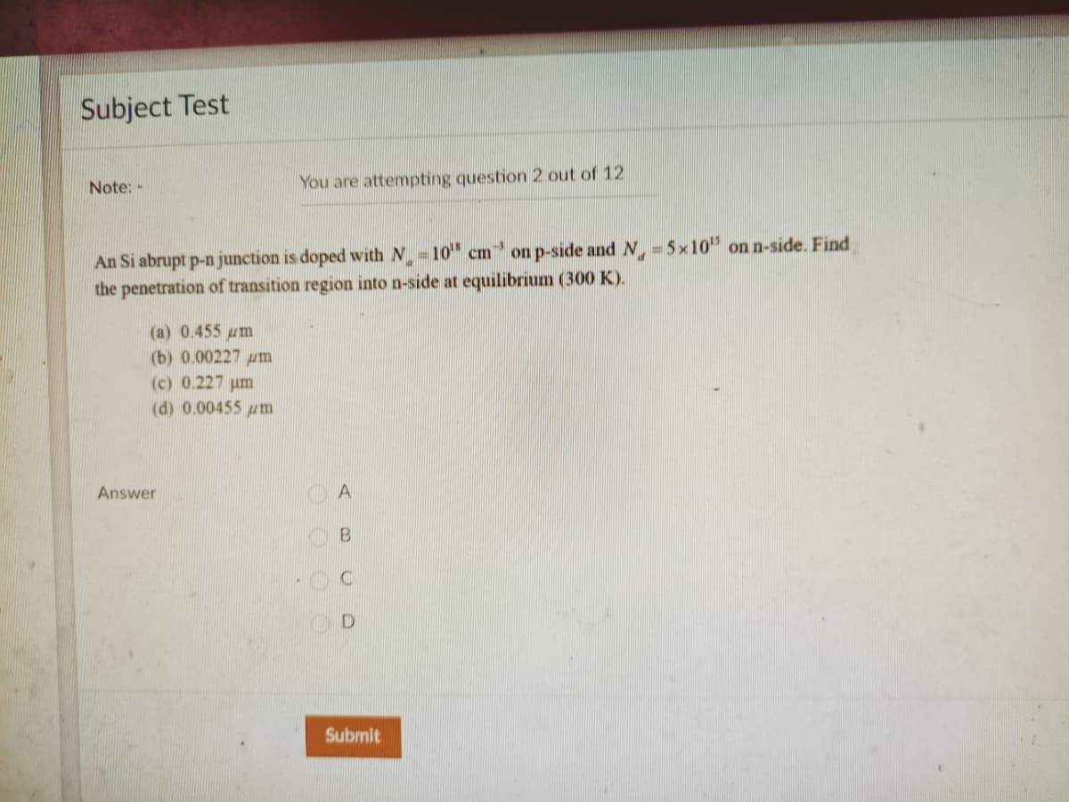
An Si abrupt p-n junction is doped with N =10" cm on p-side and N =5x10" on n-side. Find
the penetration of transition region into n-side at equilibrium (300 K).
(a) 0.455 um
(b) 0.00227 um
(c) 0.227 um
(d) 0.00455 um
Answer
A
B
Submit
Expert Solution
This question has been solved!
Explore an expertly crafted, step-by-step solution for a thorough understanding of key concepts.

This is a popular solution!

Trending now
This is a popular solution!

Step by step
Solved in 3 steps with 3 images

Knowledge Booster


Learn more about
Need a deep-dive on the concept behind this application? Look no further. Learn more about this topic, electrical-engineering and related others by exploring similar questions and additional content below.Recommended textbooks for you
Delmar's Standard Textbook Of Electricity
Electrical Engineering
ISBN:
9781337900348
Author:
Stephen L. Herman
Publisher:
Cengage Learning
Delmar's Standard Textbook Of Electricity
Electrical Engineering
ISBN:
9781337900348
Author:
Stephen L. Herman
Publisher:
Cengage Learning