Summing Amplifier R1 R2 V1 R3 Vo V2 (R21 2V,+ R3 R2V2 R, Basic Differential Amplifier Circuit R1 V1 R, (V, -v,) V out R Vout V2 R1 Instrumentation Amplifier Circuit R2 2R, 1+ R3 |(V -V,) V <)- V1 out Ro R, R2 R3 R1
Summing Amplifier R1 R2 V1 R3 Vo V2 (R21 2V,+ R3 R2V2 R, Basic Differential Amplifier Circuit R1 V1 R, (V, -v,) V out R Vout V2 R1 Instrumentation Amplifier Circuit R2 2R, 1+ R3 |(V -V,) V <)- V1 out Ro R, R2 R3 R1

Power System Analysis and Design (MindTap Course List)
6th Edition
ISBN:9781305632134
Author:J. Duncan Glover, Thomas Overbye, Mulukutla S. Sarma
Publisher:J. Duncan Glover, Thomas Overbye, Mulukutla S. Sarma
Chapter12: Power System Controls
Section: Chapter Questions
Problem 12.3P

Related questions
Question
Prove / derive the following equations
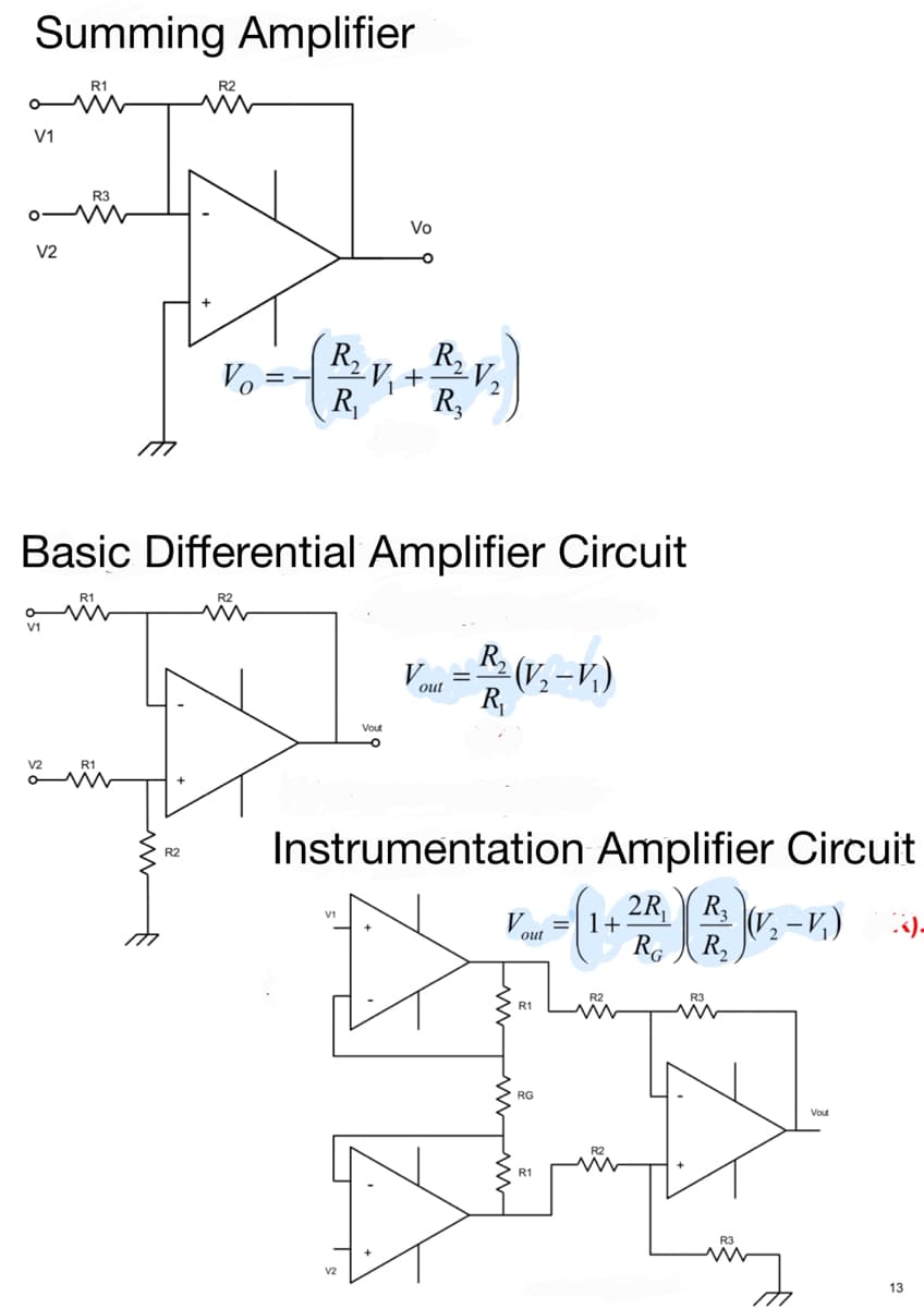
Transcribed Image Text:Summing Amplifier
R1
V1
R3
Vo
V2
Vo
(R2
R2V2
+
R,
R3
Basic Differential Amplifier Circuit
R1
R2
V1
R,
V.
(V, -v,)
R
out
Vout
Instrumentation Amplifier Circuit
R2
2R,
1+
R3
«)-
out
Ro R,
R2
R3
R1
RG
Vout
R2
R1
v2
13
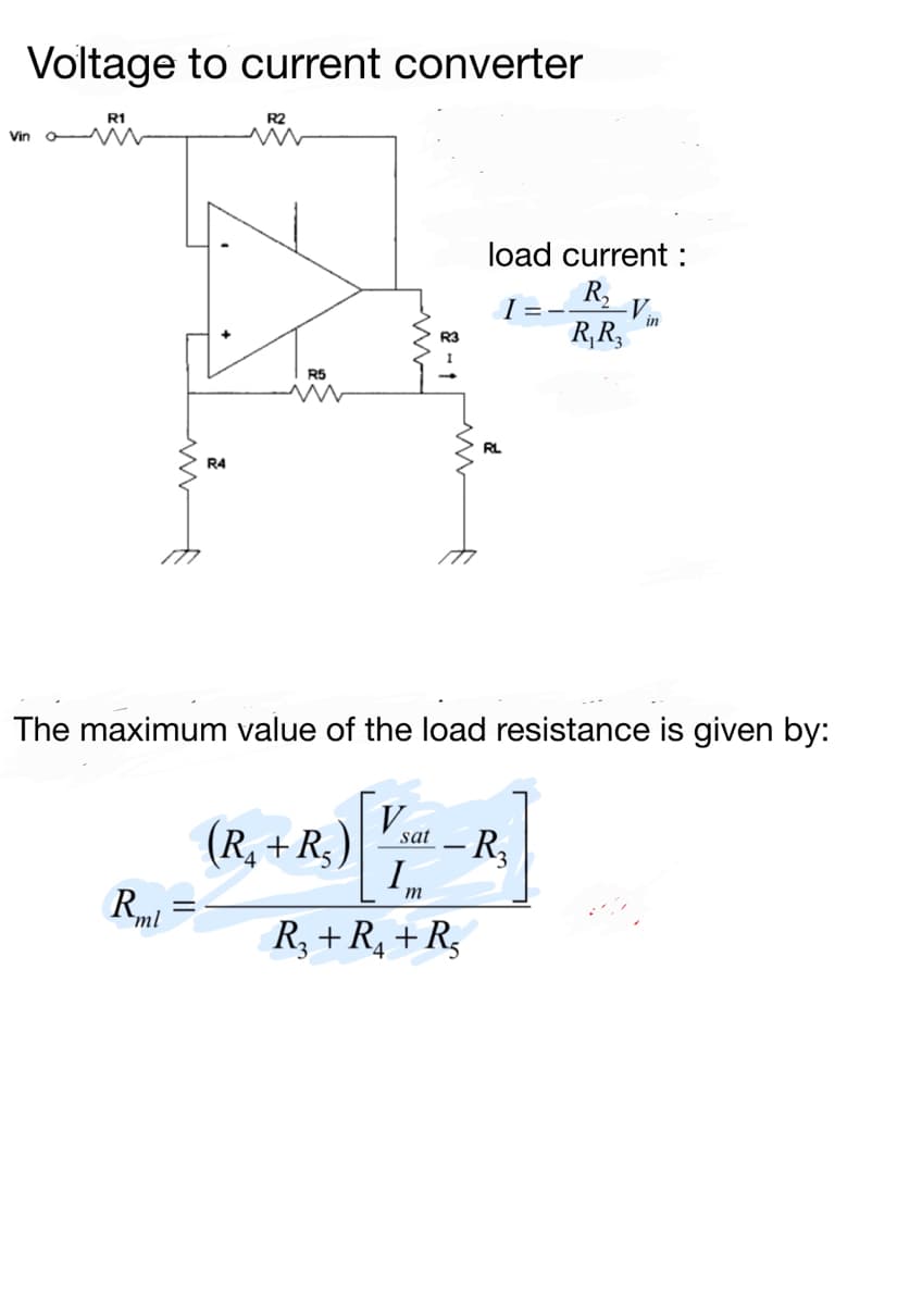
Transcribed Image Text:Voltage to current converter
R1
R2
Vin o W
load current :
R,
I=-
in
R,R,
R3
R5
RL
R4
The maximum value of the load resistance is given by:
V.
(R, + R,)
R3
sat
-
I,
m
Rml
R, + R, + R,
Expert Solution
This question has been solved!
Explore an expertly crafted, step-by-step solution for a thorough understanding of key concepts.

This is a popular solution!

Trending now
This is a popular solution!

Step by step
Solved in 3 steps with 2 images

Knowledge Booster


Learn more about
Need a deep-dive on the concept behind this application? Look no further. Learn more about this topic, electrical-engineering and related others by exploring similar questions and additional content below.Recommended textbooks for you
Power System Analysis and Design (MindTap Course …
Electrical Engineering
ISBN:
9781305632134
Author:
J. Duncan Glover, Thomas Overbye, Mulukutla S. Sarma
Publisher:
Cengage Learning
Power System Analysis and Design (MindTap Course …
Electrical Engineering
ISBN:
9781305632134
Author:
J. Duncan Glover, Thomas Overbye, Mulukutla S. Sarma
Publisher:
Cengage Learning