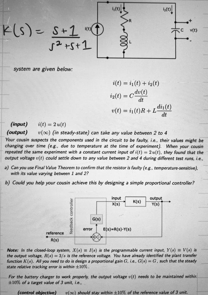
system are given below: (input) i(t) = 2u(t) (output) v(oo) (in steady-state) can take any value between 2 to 4 Your cousin suspects the components used in the circuit to be faulty, i.e., their values might be changing over time (e.g., due to temperature at the time of experiment). When your cousin repeated the same experiment with a constant current input of i(t) = 2u(t), they found that the output voltage v(t) could settle down to any value between 2 and 4 during different test runs, i.e., reference R(S) a) Can you use Final Value Theorem to confirm that the resistor is faulty (e.g., temperature-sensitive), with its value varying between 1 and 2? b) Could you help your cousin achieve this by designing a simple proportional controller? feedback controller i(t) = i₁(t) + ₂(t) i2(t) = dv(t) dt G(s) diy(t) v(t) = in(t)R + L dt error input X(s) E(s)=R(S)-Y(s) K(s) output Y(s) Note: In the closed-loop system, X(s) = I(s) is the programmable current input, Y(s) = V(s) is the output voltage, R(s) = 3/s is the reference voltage. You have already identified the plant transfer function K(s). All you need to do is design a proportional gain G, i.e., G(s) = G, such that the steady state relative tracking error is within +10%. For the battery charger to work properly, the output voltage u(t) needs to be maintained within +10% of a target value of 3 unit, i.e., (control objective) v (oo) should stay within +10% of the reference value of 3 unit.
system are given below: (input) i(t) = 2u(t) (output) v(oo) (in steady-state) can take any value between 2 to 4 Your cousin suspects the components used in the circuit to be faulty, i.e., their values might be changing over time (e.g., due to temperature at the time of experiment). When your cousin repeated the same experiment with a constant current input of i(t) = 2u(t), they found that the output voltage v(t) could settle down to any value between 2 and 4 during different test runs, i.e., reference R(S) a) Can you use Final Value Theorem to confirm that the resistor is faulty (e.g., temperature-sensitive), with its value varying between 1 and 2? b) Could you help your cousin achieve this by designing a simple proportional controller? feedback controller i(t) = i₁(t) + ₂(t) i2(t) = dv(t) dt G(s) diy(t) v(t) = in(t)R + L dt error input X(s) E(s)=R(S)-Y(s) K(s) output Y(s) Note: In the closed-loop system, X(s) = I(s) is the programmable current input, Y(s) = V(s) is the output voltage, R(s) = 3/s is the reference voltage. You have already identified the plant transfer function K(s). All you need to do is design a proportional gain G, i.e., G(s) = G, such that the steady state relative tracking error is within +10%. For the battery charger to work properly, the output voltage u(t) needs to be maintained within +10% of a target value of 3 unit, i.e., (control objective) v (oo) should stay within +10% of the reference value of 3 unit.

Introductory Circuit Analysis (13th Edition)
13th Edition
ISBN:9780133923605
Author:Robert L. Boylestad
Publisher:Robert L. Boylestad
Chapter1: Introduction
Section: Chapter Questions
Problem 1P: Visit your local library (at school or home) and describe the extent to which it provides literature...

Related questions
Question
Will Upvote for solution
Transcribed Image Text:K(s) = S+1
52 +5+1
system are given below:
i(t)
reference
R(s)
feedback controller
1₁(t)
i(t) i(t) + i2(t)
i2(t) = dv(t)
dt
G(s)
(input) i(t) = 2u(t)
(output) v(oo) (in steady-state) can take any value between 2 to 4
Your cousin suspects the components used in the circuit to be faulty, i.e., their values might be
changing over time (e.g., due to temperature at the time of experiment). When your cousin
repeated the same experiment with a constant current input of i(t) = 2 u(t), they found that the
output voltage v(t) could settle down to any value between 2 and 4 during different test runs, i.e.,
din(t)
v(t)= i(t) R+ L dt
a) Can you use Final Value Theorem to confirm that the resistor is faulty (e.g., temperature-sensitive),
with its value varying between 1 and 2?
b) Could you help your cousin achieve this by designing a simple proportional controller?
1₂(0)|
input
X(s)
error E(s)=R(S)-Y(s)
K(s)
v(t)
output
Y(s)
Note: In the closed-loop system, X(s) = I(s) is the programmable current input, Y(s) = V(s) is
the output voltage, R(s) = 3/s is the reference voltage. You have already identified the plant transfer
function K(s). All you need to do is design a proportional gain G, i.e., G(s) = G, such that the steady
state relative tracking error is within 10%.
For the battery charger to work properly, the output voltage u(t) needs to be maintained within
+10% of a target value of 3 unit, i.e.,
(control objective) v(oo) should stay within ±10% of the reference value of 3 unit.
Expert Solution
This question has been solved!
Explore an expertly crafted, step-by-step solution for a thorough understanding of key concepts.
Step 1: Summarize the given information.
VIEWStep 2: Draw the circuit in s-domain.
VIEWStep 3: Determine steady-state output voltage.
VIEWStep 4: Determine variation in resistor value.
VIEWStep 5: Determine the expression of steady-state error.
VIEWStep 6: Determine the propotional gain value.
VIEWStep 7: Determine value of resistor R.
VIEWSolution
VIEW
Step by step
Solved in 8 steps with 17 images

Knowledge Booster


Learn more about
Need a deep-dive on the concept behind this application? Look no further. Learn more about this topic, electrical-engineering and related others by exploring similar questions and additional content below.Recommended textbooks for you
Introductory Circuit Analysis (13th Edition)
Electrical Engineering
ISBN:
9780133923605
Author:
Robert L. Boylestad
Publisher:
PEARSON

Delmar's Standard Textbook Of Electricity
Electrical Engineering
ISBN:
9781337900348
Author:
Stephen L. Herman
Publisher:
Cengage Learning

Programmable Logic Controllers
Electrical Engineering
ISBN:
9780073373843
Author:
Frank D. Petruzella
Publisher:
McGraw-Hill Education
Introductory Circuit Analysis (13th Edition)
Electrical Engineering
ISBN:
9780133923605
Author:
Robert L. Boylestad
Publisher:
PEARSON
Delmar's Standard Textbook Of Electricity
Electrical Engineering
ISBN:
9781337900348
Author:
Stephen L. Herman
Publisher:
Cengage Learning
Programmable Logic Controllers
Electrical Engineering
ISBN:
9780073373843
Author:
Frank D. Petruzella
Publisher:
McGraw-Hill Education

Fundamentals of Electric Circuits
Electrical Engineering
ISBN:
9780078028229
Author:
Charles K Alexander, Matthew Sadiku
Publisher:
McGraw-Hill Education

Electric Circuits. (11th Edition)
Electrical Engineering
ISBN:
9780134746968
Author:
James W. Nilsson, Susan Riedel
Publisher:
PEARSON

Engineering Electromagnetics
Electrical Engineering
ISBN:
9780078028151
Author:
Hayt, William H. (william Hart), Jr, BUCK, John A.
Publisher:
Mcgraw-hill Education,