t=0- R=128.852 
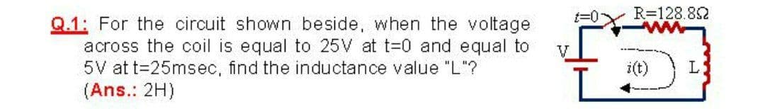
Q.1: For the circuit shown beside, when the voltage across the coil is equal to 25V at t-0 and equal to 5V at t=25msec, find the inductance value "L"? (Ans.: 2H) V i(t) L
Q: A coil having a 240V source has a current of 10.5 A when the frequency is set to 60 Hz. When the…
A:
Q: What is the ripple voltage (in Vrms) of a capacitor filter for a peak rectified voltage of 34 V,…
A: The type of rectifier is not given. Assuming it as full wave rectifier. For a full wave rectifier,…
Q: Find the equivalent capacitance (µF) seen at the terminals of the circuit below. 50µF 60µF Ceq 70µF…
A: By series and parallel combination of capacitor we will find out equivalent capacitance .
Q: A coil of inductance 100 mH and resistance 800 ohm is connected in parallel with a variable The…
A: The required parameters can be calculated when the circuit reaches resonance. At resonance the…
Q: 102 Q.7: By using classical method find the transient total current equation for the circuit shown…
A:
Q: A coil of resistance 20 Ω and inductance 300 mH is connected in parallel with a capacitor of 200μF.…
A:
Q: What is incorrect about the RLC AC Circuit shown? 1 The power dissipation through the (ideal)…
A:
Q: Q1) Design of lead copmpensator to obtain the required response of damping ratio=0.2 &Wn=5.1.
A:
Q: Fox the Coupled Circuit shown, find mutual inductance "M" the value of and put the dots on the Coil…
A: Let us assume the coils are connected in cumulative series. Let L be the equivalent inductance of…
Q: of Rin Vin- di t) =0 dt Care fully examine the opump RLC electrical circuit given in the figure…
A:
Q: Power factor 90 to 100% 88 to <90% 85 to <88% 80 to <85% 75 to < 80% 70 to < 75% 65 to < 70% 60 to…
A: In this question we need to find the smallest KVAR required to reduce the surcharge to 0%
Q: Design a second order LPF, with unity dc gain, to realize the following natural modes P2 = 10…
A: Low pass filter with passive components:…
Q: Q2) For the circuit shown below find the following: (1) CB value, (2) effective total capacitance of…
A: (1) In the given circuit, the reactance of capacitor CB is low enough for the AC signal to pass…
Q: An LC circuit like the one in the figure below contains an 75.0 mH inductor and a 30.0 µF capacitor…
A: Hello. Since your question has multiple sub-parts, we will solve first three sub-parts for you. If…
Q: Q.18 ** *** [ The current in a coil of self-inductance of 4H changes from 10A to 2A in t seconds and…
A: Given: Self inductance of coil, L = 4 H Current changes from 10 A to 2 A, so ∆i=10-2 A=8 A Induced…
Q: 2. In the circuit below, find the value of the voltage across the capacitor assuming that the value…
A:
Q: In the circuit as shown, assume all parameters except C are given. Find (a) the current in the…
A: Hello. Since your question has multiple sub-parts, we will solve the first three sub-parts for you.…
Q: Impedance Z = Ω Source current Is A Apparent power S = VA Resistor current IR = А Active power PR =…
A: The solution is given below
Q: A coil of resistance 200 and inductance 10 mH is in series with a capacitance and is supplied with a…
A: Given, A coil with series RLC circuit having, Resistance, R = 20 Ω Inductance, L = 10 mH The maximum…
Q: Find the impedance theoretically of a wire if it carries the frequency 10 kHz have a voltage is 8v,…
A:
Q: The input voltage of the following figure is V,=220 V with load resistance of R=70. The load and…
A: Information about the given circuit are Input voltage Vs=220 Volts. Thyristor operating frequency…
Q: 8) A coil having resistance R and inductance 80mH is connected in parallel with a 5 nF capacitor…
A: “Since you have posted a question with multiple sub-parts, we will solve first three sub-parts for…
Q: A source delivers an AC voltage of the form AV = 198 sin( 51 nt), where AV is in volts and t is in…
A: Here, we have given some information about the voltage delivered by the voltage source. The maximum…
Q: An LC-circuit like the one shown in the figure contains an 75.0-mH inductor and a 20-μF capacitor…
A:
Q: A coil has a time constant of 1s and an inductance of 10 H.Find (1) the value of current 0. 1s after…
A: Circuit shown is actually a simple RL circuit with source provided So it has steady state values...
Q: Electrical Engineering Gcopper = 5.813×10" (Nm)', µo=4xx107 H/m, o-8.85x10¹² F/m a) Find the high…
A: Given: Consider the parameters: σcopper=5.813×10⁷ Ωm-1μo=4π×10-7 H/mεo=8.85×10-12 F/m To find: (a)…
Q: of capacitance C = 2πT A series LCR circuit consists of an inductor of self inductance L=H, a…
A:
Q: Q-3) Find the range of gain, K, for the system that will cause the system to be stable, unstable,…
A: In this question, We need to find the range of the K for given system is stable , unstable, and…
Q: Ina series RLC circuit, the supply voltage is 120 volts 60-cyle, the resistance of resistoris 10…
A:
Q: A pure inductance of L = 144 mH is connected to a V = 102 V, 50 Hz supply. The current taken by the…
A:
Q: Design the circuit shown so that ve(1) +Aje +Aze¬t V for t>0 Determine the values of the unspecified…
A: When the circuit reaches steady state after t=0, the capacitor acts like an open circuit and…
Q: Design a second order LPF, with unity de gain, to realize the following natural modes P1,2 = 10¹…
A:
Q: A pure inductance of L = 144 mH is connected to a V = 112 V, 50 Hz supply. The current ta by the…
A:
Q: Problem: A coil of pf 0.6 is in series with a 100μF capacitor. When connected to a 50Hz supply, the…
A: Solution !!
Q: An inductance comparison bridge has L1=100µH and R4=10KN. When neasuring an unknown inductance, null…
A: Data given L1=100μHR1=37.1ΩR3=27.93KΩR4=10KΩf=1 MHz=106Hz
Q: Acontrol system is shown in figure belows. Find K and Ke so that the damping ratio 2.0.6 and damped…
A: Given data : Damping ratio ξ=0.6 Damped natural frequency ωd=10rad/s
Q: Q4: For the circuit shown below, determine the coupling coefficient and the ehergy stored in the…
A:
Q: Lesson= Second Order Transient Response A 24-V battery is connected in seires with a 1-Henry…
A:
Q: An RLC circuit consists of a 150-Ω resistor, a 21.0-μF capacitor, and a 460-mH inductor connected in…
A: Inductive reactance, Capacitive reactance Therefore, the impendence
Q: A 10 Q resistor is placed in series with a coil of self resistance RL Ans: and inductance L and a…
A: As per the guidelines of Bartley we supposed to answer first three subpart only for solution of…
Q: Consider an LCR circuit with inductance 1 H, resistance 22, capacitance 4 Fand a voltage sin2t. Find…
A: In RLC circuit considering the loop current is i, applying the Kirchhoff’s voltage law in the…
Q: A coil of resistance 20 02 & inductance 0.2 H is connected in series with 100µF capacitor across a…
A:
Q: A pure inductance of L = 152 mH is connected to a V = 106 V, 50 Hz supply. The current taken by the…
A: Given data : V= 106 VL=152 mH =0.152 Hf= 50 Hz
Q: A circuit is designed with an AC source of max voltage 12 and frequency 60 Hz. The circuit has a…
A:
Q: The input voltage of the following figure is Vs=200 V with load resistance of R=50. The load and…
A:
Step by step
Solved in 2 steps with 2 images
- A coil of inductance 100 mH and resistance 800 ohm is connected in parallel with a variable The capacitor is across a 12V, 5 kHz supply. Determine for the condition when the supply current is a minimum: (a) the capacitance of the capacitor, (b) the dynamic resistance, (c) the supply current, and (d) the Q-factorLet Vs=530tᶾ v, leg t >0 and iL (0) = 1 A, in the circuit shown, at t=0.2s, determine the values of the energy stored in the capacitor and the coil. The circuit is in the attached image.The capacitor of external defibrillator must be loaded at 1500V, in order to generate a two-phase wave of 150 J.Considering a transthoracic impedance is 80ohms and a capacitance of 30 000 uF. 3- What is the energy of the capacitor?4- What is the internal impedance of the defibrillator in the previous cases?
- Ex : For the circuit shown in the figure below : 1. Find the mathematical expression for the transient behaviour of the voltage across the capacitor as well as the current of the capacitor if the capacitor was initially uncharged and the switch is closed at position 1 when t - o sec . 2. Find the mathematical expression for Vc and is if the switch is moved to position 2 at t = 10msec . 3. Find the mathematical expressions for Vc and ic if the switch is moved to position 3 at t = 20msec 4. Plot the waveforms of the Vc and is obtained from the parts 1 to 3 . R ic 20 kΩ 20 E 12 V C 0.05 uF vc R , 310 ΚΩ TWhat is the ripple voltage (in Vrms) of a capacitor filter for a peak rectified voltage of 34 V, capacitor C = 561 µF, and a load current of 52 mA? No need to show your solution. Just write your numeric answer on the space provided. Round off your answer to 2 decimal places.Q5. For an exhibition project you are designing a circuit of signal processor which can be connected to 230V, 50 Hz supply have a 5.0 H inductor, 80 μ F capacitor and 40Ω resistor kept in series. How can you evaluate the rms current and average power delivered to the circuit? Based on your observation, evaluate the potential drop across capacitance and inductor. Comment about that r m s voltage found in this circuit is less than peak voltage? Justify it with your answer. If you remove the inductor and connect a bulb in series with a capacitor. What will happen to the brightness of bulb if it is connected to DC source and then to an AC source. Assess and find reason for your observations in each case.
- A 1-H inductor and a 2.5-mF capacitor is connected in series. The combination is connected across a voltage emf(t) = 12 V. What is the RMS magnitude of the oscillating current, in amperes? Assume initial current of 2 A but capacitor's initial charge is 0 C.12. 7.12 In the circuit , let Ig represent the dc current source, σrepresent the fraction of initial energy stored in the inductor that isdissipated in to seconds, and L represent the inductance. 1. a) Show thatR=Lln[1/(1−σ)]2toA circuit is designed with an AC source of max voltage 12 and frequency 60 Hz. The circuit has a resistance of 1050 Ohms, an inductance of 0.06 Henrys, and a capacitance of 0.009 coulombs per volt. - omega for source in rad/s? - omegaR for circuit? -XL? -XC? -phi in radians? -Z? -imax?
- What is incorrect about the RLC AC Circuit shown? 1 The power dissipation through the (ideal) capacitor is vanishing. 2 The current leads the voltage across the capacitor by 90deg. 3 The voltage across the inductor leads the current by 90deg. 4 If the AC source is replaced by a constant DC source, after a very longtime, the voltage across the inductor vanishes. 5 If the AC source is replaced by a constant DC source, after a very longtime, the voltage across the capacitor will be equal to that across theresistor.A resistor, an inductor, and a capacitor are connected in parallel to an ac source with voltage amplitude V and angular frequency v. Let the source voltage be given by v = Vcosvt. (a) Show that each of the instantaneous voltages vR, vL, and vC at any instant is equal to v and that i = iR + iL + iC, where i is the current through the source and iR, iL, and iC are the currents through the resistor, inductor, and capacitor, respectively. (b) What are the phases of iR, iL, and iC with respect to v? Use current phasors to represent i, iR, iL, and iC. In a phasor diagram, show the phases of these four currents with respect to v. (c) Use the phasor diagram of part (b) to show that the current amplitude I for the current i through the source is I = √(I2R) + (IC - IL)2 . (d) Show that the result of part (c) can be written as I = V/Z, with 1/Z = √ (1/R2) + [ωC - (1/ωL)]2.An amateur radio operator wishes to build a receiver thatcan tune a range from 14.0 MHz to 15.0 MHz. A variablecapacitor has a minimum capacitance of 86 pF. (a) Whatis the required value of the inductance? (b) What is themaximum capacitance used on the variable capacitor?