TABLE OF RESULTS Table 6.1 Voltmeter Reading Branch Resistors Voltmeter Reading (V) R1 R2 R3 R4 Rs Table 6.2 Ammeter Reading Branch Resistors Ammeter Reading (I, mA) RI R2 R3 R4 Rs Table 6.3 Computed Value Computed Value (Ohms) Voltage value (V) Branch Current Value Actual value Resistor R1 R2 R3 |(mA) (V) R4 Rs RT COMPUTATIONS:
TABLE OF RESULTS Table 6.1 Voltmeter Reading Branch Resistors Voltmeter Reading (V) R1 R2 R3 R4 Rs Table 6.2 Ammeter Reading Branch Resistors Ammeter Reading (I, mA) RI R2 R3 R4 Rs Table 6.3 Computed Value Computed Value (Ohms) Voltage value (V) Branch Current Value Actual value Resistor R1 R2 R3 |(mA) (V) R4 Rs RT COMPUTATIONS:

Chapter25: Television, Telephone, And Low-voltage Signal Systems
Section25.2: Telephone System
Problem 2R: At what height are the telephone outlets in this residence mounted? Give measurement to center....

Related questions

Question
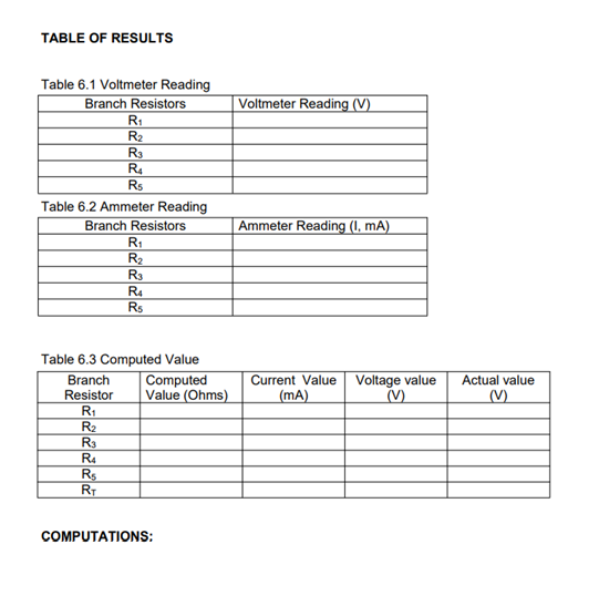
Transcribed Image Text:TABLE OF RESULTS
Table 6.1 Voltmeter Reading
Branch Resistors
Voltmeter Reading (V)
R1
R2
R3
R4
Rs
Table 6.2 Ammeter Reading
Branch Resistors
Ammeter Reading (I, mA)
RI
R2
R3
R4
Rs
Table 6.3 Computed Value
Computed
Value (Ohms)
Voltage value
(V)
Branch
Current Value
Actual value
Resistor
R1
R2
R3
|(mA)
(V)
R4
Rs
RT
COMPUTATIONS:
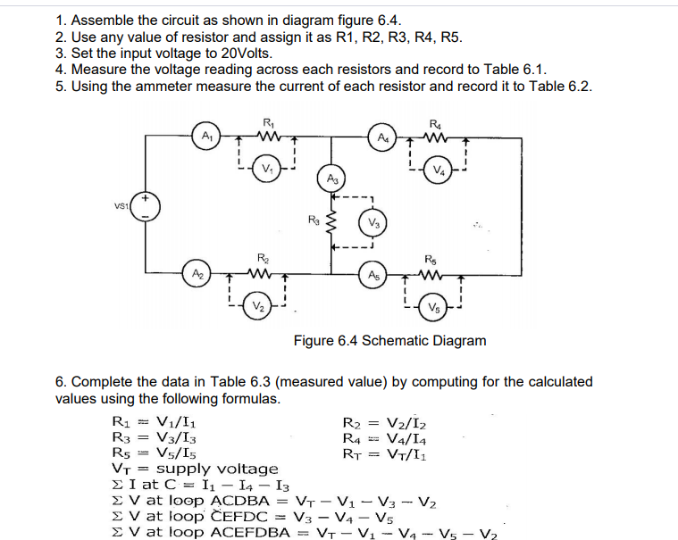
Transcribed Image Text:1. Assemble the circuit as shown in diagram figure 6.4.
2. Use any value of resistor and assign it as R1, R2, R3, R4, R5.
3. Set the input voltage to 20Volts.
4. Measure the voltage reading across each resistors and record to Table 6.1.
5. Using the ammeter measure the current of each resistor and record it to Table 6.2.
R,
R.
A,
A
V4
As
Ra
V3
Rs
A2
As
V2
Vs
Figure 6.4 Schematic Diagram
6. Complete the data in Table 6.3 (measured value) by computing for the calculated
values using the following formulas.
R1 = V1/I1
R3 = V3/I3
R5 = V5/I5
VT = supply voltage
E I at C = I1 – I4 – I3
E V at loop ACDBA
E V at loop ĈEFDC
E V at loop ACEFDBA
R2
R4
RT
V2/I2
V4/I4
VT/I1
%3D
:VT - V1 – V3 - V2
V3 - V4 - Vs
VT - Vị - V4 - V5 - V2
Expert Solution
This question has been solved!
Explore an expertly crafted, step-by-step solution for a thorough understanding of key concepts.

This is a popular solution!

Trending now
This is a popular solution!

Step by step
Solved in 4 steps with 4 images

Knowledge Booster


Learn more about
Need a deep-dive on the concept behind this application? Look no further. Learn more about this topic, electrical-engineering and related others by exploring similar questions and additional content below.Recommended textbooks for you
EBK ELECTRICAL WIRING RESIDENTIAL
Electrical Engineering
ISBN:
9781337516549
Author:
Simmons
Publisher:
CENGAGE LEARNING - CONSIGNMENT

Power System Analysis and Design (MindTap Course …
Electrical Engineering
ISBN:
9781305632134
Author:
J. Duncan Glover, Thomas Overbye, Mulukutla S. Sarma
Publisher:
Cengage Learning

Delmar's Standard Textbook Of Electricity
Electrical Engineering
ISBN:
9781337900348
Author:
Stephen L. Herman
Publisher:
Cengage Learning
EBK ELECTRICAL WIRING RESIDENTIAL
Electrical Engineering
ISBN:
9781337516549
Author:
Simmons
Publisher:
CENGAGE LEARNING - CONSIGNMENT
Power System Analysis and Design (MindTap Course …
Electrical Engineering
ISBN:
9781305632134
Author:
J. Duncan Glover, Thomas Overbye, Mulukutla S. Sarma
Publisher:
Cengage Learning
Delmar's Standard Textbook Of Electricity
Electrical Engineering
ISBN:
9781337900348
Author:
Stephen L. Herman
Publisher:
Cengage Learning